illumination cameras microscopy / objectives filters / accessories liquid lens / specialty telecentric fixed focal length resource guide
Getting Started: Best Practices for Better Imaging
4 +44(0) 1904 788600 | Edmund Optics® targets Whether your application is in machine vision, life sciences, security,
or traffic solutions, understanding the fundamentals of imaging
technology significantly eases the development and deployment
of sophisticated imaging systems. While advancements in sensor
and illumination technologies suggest limitless system capabilities,
there are physical limitations in the design and manufacture
of these technologies. Optical components are not an exception to
such limitations, and optics can often be the limiting factor of system
performance. The content provided in this guide is designed to
help specify an imaging system, maximize system’s performance,
and minimize cost.
Imaging Resource Guide
Compiled are several simple best practices for creating sophisticated,
cost-effective imaging systems useful to most applications.
While the list is nearly exhaustive and should be used when designing
any imaging system, each application is unique and may require
extra consideration.
u #1: Allow ample room for the imaging system.
Understanding a system’s space requirements before building is especially
crucial for high-resolution and high-magnification requirements.
Recent advancements in camera technology have yielded exceptional
consumer cameras in small sizes. However, these advancements do
little to benefit even intermediate-level industrial imaging systems—
partially because of size limitations. Many applications can require
complex light geometries, large diameter-long length lenses, and
large cameras, in addition to cabling and power sources required to
operate equipment. Avoid sacrificing performance by considering
spatial feasibility during project planning. Specify the requirements
of a project’s vision system first. It is typically easier to arrange electronics
and mechanics around the optical portion than otherwise. It
is important to note that the illumination scheme is part of the vision
system and that the object under inspection may require the use
of large or numerous light sources, such as a diffuse dome (see Best
Practice #4).
u #2: Don’t believe your eyes.
The human eye and brain work together to form an extremely advanced
imaging and analysis system capable of filling in information
not necessarily present. Additionally, the way in which humans see
and process contrast is fundamentally different than imaging systems.
Software analysis must be used to ensure image quality and performance
requirements are met. Images that look good to a human may
not actually be sufficient.
u #3: Don’t get too close.
Due to the constraints of physics, attempting to image fields of view
(FOV) too large, relative to a lens’s working distance (WD), places excessive
demands on the design of the optical components, decreasing
system performance and increasing the need for imaging processing
and the time in which processing is done. It is recommended that
a lens be chosen such that the WD is roughly two to four times as long
as the desired FOV width to maximize performance while minimizing
cost and complexity. Remember Best Practice #1 and consider the imaging
system’s space requirement before building the system.
This practice also applies to the relationship between sensor size and
focal length. It is best to have focal length to sensor diagonal ratios of
two to four (2:1 to 4:1) to maximize performance.
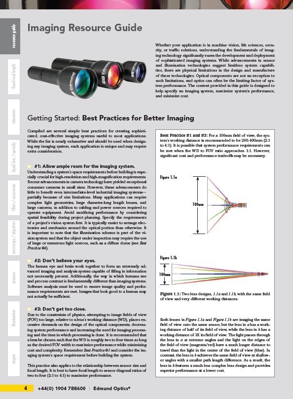
Best Practice #1 and #3: For a 100mm field of view, the system’s
working distance is recommended to be 200-400mm (2:1
to 4:1). It is possible that system performance requirements can
be met when the WD to FOV ratio approaches 1:1. However,
significant cost and performance tradeoffs may be necessary.
Figure 1.1a
Figure 1.1b
100mm
100mm
Figure 1.1: Two lens designs, 1.1a and 1.1b, with the same field
of view and very different working distances.
Both lenses in Figure 1.1a and Figure 1.1b are imaging the same
field of view onto the same sensor, but the lens in a has a working
distance of half of its field of view, while the lens in b has a
working distance of 3X its field of view. The light passes through
the lens in a at extreme angles and the light on the edges of
the field of view (magenta/red) have a much longer distance to
travel than the light in the center of the field of view (blue). In
contrast, the lens in b achieves the same field of view at shallower
angles with a smaller path length difference. As a result, the
lens in b features a much less complex lens design and provides
superior performance at a lower cost.