C-Mount
Camera
190mm
Extension Tube
MT-1/MT-2 C-Mount
Adapter #58-329
Section 9.2: Using Tube Lenses with Infinity Corrected Objectives
The distance between an infinity corrected objective and the tube lens (L) can be varied from the recommended or optimal, but this will affect the
image field diameter (Ø). Equations 9.1 and 9.2 are approximation formulas to determine the relation between Ø and L.
Example:
Using an M Plan APO 10X objective (#46-144), MT-1 tube lens (#54-774), and a 2/3" sensor camera, what is the maximum spacing between the tube
lens and objective without vignetting? The focal length of the objective (f1) is 20mm and NA is 0.28, so the exit pupil diameter can be calculated:
A 2/3" image sensor features an 11mm diagonal, therefore Ø needs to be at least 11mm. The focal length of the MT-1 tube lens is 200mm and the
entrance pupil diameter is 24mm. Therefore, L = ((24 – 11.2) × 200)/11 = 232.7mm
As long as the spacing between the tube lens and objective is less than 232.7mm, there will be no vignetting.
3.5mm
3.5mm
25.0mm
600 650 700
www.edmundoptics.co.uk/imaging 131
objectives resource guide telecentric liquid lens / specialty cameras illumination targets
fixed focal length filters/accessories microscopy /
(Ø2 – Ø1) × f2
Equation 9.1: Ø1 = 2 × f1 x NA Equation 9.2: L =
Ø
Ø1 = 2 × 20 × 0.28 = 11.2mm
Section 9.3: Fluorescence Filters for Microscopy
Camera
Emission
Filter
Dichroic
Filter
Slide
Excitation
Filter
Mercury
Arc Lamp
25.0mm
35.6mm
1.05mm
Figure 9.4
Figure 9.4: Basic fluorescence microscope setup.
100
90
80
70
60
50
40
30
20
10
0
400 450 500 550
Wavelength (nm)
Absorption (Normalized)
Fluorophore Absorption and Emission Profiles
750
Absorption Spectral Profile
Emission Spectral Profile
Figure 9.5
Figure 9.5: Typical excitation and emission profile.
Fluorescence microscopy is a microscopy technique that uses fluorescence,
which is induced using fluorophores, as opposed to absorption,
scatter, or reflection. A fluorophore is a fluorescent dye used
to mark proteins, tissues, and cells with a label for examination by
fluorescence microscopy. A fluorophore works by absorbing energy
of specific wavelengths, commonly referred to as the excitation range,
and re-emitting that energy in another specific wavelength region, referred
to as the emission range.
Fluorescence microscopy systems like an epifluorescent microscope
can be simple, whereas confocal or multiphoton systems can be very
complex. However, all fluorescence microscopes share the same basic
concept: excitation energy illuminates a sample which releases
weak but quantifiable emission energy. The excitation and emission
wavelengths do not share the same center wavelength. This allows
specialized filters to increase the overall contrast and signal.
The most basic concept and schematic is seen in Figure 9.4. A filter
arrangement is constructed of three filter types: an excitation filter,
a dichroic filter, and an emission filter. The excitation filter is placed
within the illumination path of a fluorescence microscope and filters
out all wavelengths of the light source except for the fluorophore excitation
range. The dichroic filter is placed between the excitation filter
and emission filter at a 45° angle and reflects the excitation signal
towards the fluorophore while transmitting the emission signal toward
the detector. The emission filter is placed within the imaging path of
the fluorescence microscope and filters out the excitation range of
fluorophore while transmitting the emission range.
Figure 9.5 shows a typical excitation, emission profile. The absorption
and emission profiles share common wavelengths which is one
reason why high-quality filters with high transmission, narrow bandwidths,
high optical densities, and sharp cut-on and cut-off bands are
needed. Using low quality filters can ultimately damage the sample,
specimen, or expensive sensors.
Mitutoyo
Objective
MT-1/MT-2 Tube Lens
#54-774/#56-863
Mitutoyo C-Mount
Adapter #55-743
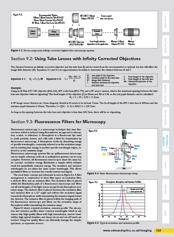
Recommended Option
100mm C-Mount Extension Tube #54-633
50mm C-Mount Extension Tube #54-632
30-50mm, C-Mount Fine Focus Tube #03-625
Comes apart
into two pieces
Extension
Tubes
Exact length selection
dependent on the application
Figure 9.3
Figure 9.3: Seven-component infinity corrected digital video microscope system.
Ø1 : exit pupil of the objective
Ø2 : entrance pupil of the tube lens
Ø : image field diameter
L : distance between the objective
and tube lens
f1 : focal length of the objective
f2 : focal length of the tube lens
NA : Numerical Aperture of the
objective
/imaging