targets illumination cameras microscopy / objectives filters / accessories liquid lens / specialty telecentric fixed focal length resource guide 126 +44(0) 1904 788600 | Edmund Optics® Color Filters
Consider the example shown in Figure 5, where gel capsules are being
inspected. As shown, two red capsules are on the outer sides of a pair
of green capsules and under a white light backlight. This is a sorting
application where the pills need to be separated by color to reach their
respective locations. Imaging the capsules with a monochrome camera
(Figure 6) provides a contrast between the green and red capsules of
only 8.7%, which is below the minimum advisable contrast of 20%.
In this particular example, minor fluctuations in ambient light, such
as individuals walking past the system, can decrease the already low
contrast value of 8.7% enough so that the system is no longer capable
of operating properly. Several solutions to this problem exist: a bulky
and costly light baffling system can be built to completely enclose the
inspection system, the entire lighting scheme of the system can be
reworked, or a filter can be added to enhance the contrast between
the green and red pills. In this instance, the simplest and most cost
effective solution is to utilize a green colored glass filter in order to
improve the contrast between the two different colored capsules. As
shown in Figure 6, the contrast improves from 8.7% to 86.5%: an increase
of nearly a factor of 10.
Neutral Density Filters
Neutral density filters are used in certain applications where it is advantageous
to have additional control over the brightness of an image
without changing the exposure time or adjusting the f/#. Although
there are two primary types of neutral density filters (absorbing and
reflecting), effect on the image is the same: uniformly lower the light
that is transmitted through the lens and onto the sensor. For applications
like welding, where the imager can be overloaded regardless of
the exposure time, neutral density filters can provide the necessary
drop in throughput without needing to change the f/# (which can impact
the resolution of the system). Specialty neutral density filters, like
apodizing filters, exist to help with hotspots in the center of an image
caused by a harsh reflection from an object, but the optical density
decreases with radial distance away from the center of the filter.
Polarizing Filters
Polarization filters are another common type of filter used in machine
vision applications that allow better imaging of specular objects. To
properly use polarizing filters, both the light source and the lens must
have polarization filters on them. These filters are called the polarizer
and analyzer, respectively. Figure 7 shows an example of how polarization
filters can make a difference when viewing specular objects. In
Figure 7a, a CCD imager is being inspected with brightfield illumination
and Figure 7b shows the same illumination setup with a polarizer
on the light source and an analyzer on the lens.
As shown in Figure 7b, augmenting the system with polarizers provides
superior performance as the harsh reflections are absorbed by the filter
on the lens. To ensure the maximum rejection of unwanted glare, the polarization
axis of the polarizer must be angled 90° from the polarization
angle of the polarizer on the lens. Otherwise, the lens will still transmit
some of the harshly reflected light into the system, causing glare.
It is critical to understand that filters exist to manipulate the contrast
of an image to help increase the accuracy of the imaging system.
Whether filtering by color or by polarization, each filter exists to solve
a unique problem; it is important to understand which filters should
be used for specific applications.
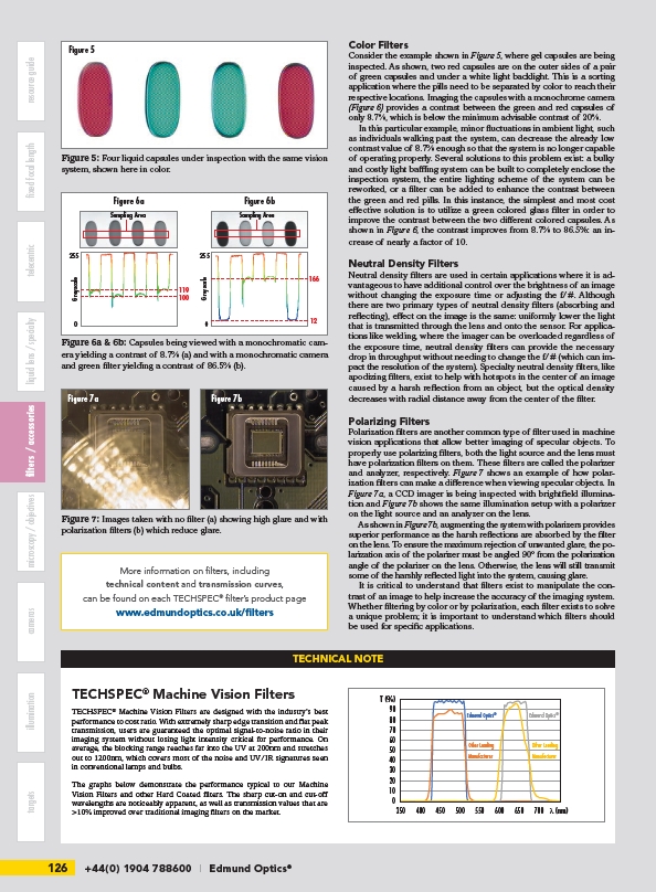
Figure 5
Figure 5: Four liquid capsules under inspection with the same vision
system, shown here in color.
Figure 6a Figure 6b
255
Greyscale
0
119
100
Sampling Area
255
Greyscale
0
Figure 6a & 6b: Capsules being viewed with a monochromatic camera
yielding a contrast of 8.7% (a) and with a monochromatic camera
and green filter yielding a contrast of 86.5% (b).
166
12
Figure 7a Figure 7b
Figure 7: Images taken with no filter (a) showing high glare and with
polarization filters (b) which reduce glare.
More information on filters, including
technical content and transmission curves,
can be found on each TECHSPEC® filter’s product page
www.edmundoptics.co.uk/filters
TECHNICAL NOTE
TECHSPEC® Machine Vision Filters
TECHSPEC® Machine Vision Filters are designed with the industry’s best
performance to cost ratio. With extremely sharp edge transition and flat peak
transmission, users are guaranteed the optimal signal-to-noise ratio in their
imaging system without losing light intensity critical for performance. On
average, the blocking range reaches far into the UV at 200nm and stretches
out to 1200nm, which covers most of the noise and UV/IR signatures seen
in conventional lamps and bulbs.
The graphs below demonstrate the performance typical to our Machine
Vision Filters and other Hard Coated filters. The sharp cut-on and cut-off
wavelengths are noticeably apparent, as well as transmission values that are
>10% improved over traditional imaging filters on the market.
T (%)
90
80
70
Edmund Optics® Edmund Optics®
60
50
40
30
20
10
0
350 400 450 500 550 600 650 700
λ (nm)
Other Leading
Manufacturer
Other Leading
Manufacturer
Sampling Area
/filters