/ accessories resource guide
targets illumination cameras liquid lens / specialty telecentric fixed focal length
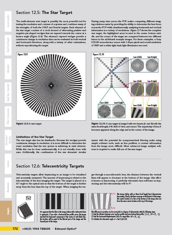
Figure 12.9
172 +44(0) 1904 788600 | Edmund Optics® filters microscopy /
objectives
The multi-element start target is possibly the most powerful tool for
testing the resolution and contrast of a system and combines many of
the strengths of both the USAF and Ronchi targets. Each element of
the star target consists of a circle formed of alternating positive and
negative pie-shaped wedges that are tapered towards the center at a
known angle (Figure 12.9). The element’s tapered wedges provide a
continuous change in resolution that can be evaluated in both vertical
and horizontal directions, along with a variety of other orientations,
without repositioning the target.
Limitations of the Star Target
The star target also has its drawbacks. Because the wedges provide
continuous changes in resolution, it is more difficult to determine the
exact resolution that the test system is achieving at each element.
While this can be done mathematically, it is not visually done with
ease. Additionally, the combination of the star elements’ circular
Telecentricity targets allow keystoning in an image to be visualized
and accurately measured. The amount of keystoning is related to the
telecentricity of the lens imaging the target. The target is placed at a
45° angle to the optical axis so that the bottom of the target is further
away from the lens than the top of the target. When imaging the target
Having many stars across the FOV makes comparing different imaging
solutions easier by providing the ability to determine the best focus
across the FOV while simultaneously analyzing horizontal and vertical
information at a variety of resolutions. Figure 12.7 shows the complete
star target; the highlighted areas located in the center, bottom middle,
and the corner of the target are compared between two different
lenses in the additional example images. For these examples, a Sony
ICX625 monochrome sensor with 3.45μm pixels and a total resolution
of 5MP and a white light back light illuminator are used.
Lens A (left) Lens B (right)
Lens A (left) Lens B (right)
Figure 12.10
Lens A (left) Lens B (right)
Lens A (left) Lens B (right)
nature with the potential for nonsymmetrical blurring make using
simple software tools, such as line profilers, to extract information
from the image more difficult. More advanced image analysis software
is required to make full use of the star target.
through a non-telecentric lens, the distance between the vertical
lines will appear to decrease at the bottom of the image; this effect
is known as keystoning. A perfectly telecentric lens will have no keystoning
and the telecentricity will be 0°.
Section 12.5: The Star Target
Figure 12.9: A star target.
Figure 12.10: A star target is imaged with two lenses (A and B) with the
same focal length, f/#, field of view, and sensor. The superiority of lens A
becomes apparent along the edge and in the corner of the image.
Section 12.6: Telecentricity Targets
It is apparent that the blur in this image (taken with a telecentric lens)
is symmetric. If you take a horizontal line profile across the image
and find the horizontal component of the center of each black line,
the location will be equal in the blurred part of the image and the
focused part of the image.
lens
This image (taken with an 8mm focal length lens) demonstrates
keystoning. Clearly, the lines converge at the bottom of the image.
The center location of a line at the bottom of the image does not
have the same center location at the top of the image.
(Y1, X1)
(Y2, X2)
This difference in position can be converted to a degree of telecentricity with the following steps:
1) Find the distance between your top line profile and your bottom line profile, Y1 & Y2 ΔY = (Y1 - Y2)
2) Find the horizontal displacement (ΔX) of a target line: ΔX = |X1 - X2|
3) Calculate the telecentric angle: q = Tan-1(ΔX/ΔY)