illumination cameras microscopy / filters / accessories resource guide
objectives liquid lens / specialty telecentric fixed focal length
Section 9: Understanding Microscope Objectives
More information on infi nity corrected objectives can be found at www.edmundoptics.co.uk/objectives
Figure 9.1 Figure 9.2
Sensor or Eyepiece
Image Plane
Microscope Tube Lens
Objective
Achromatic
Triplet
Achromatic
Doublet
Group
Meniscus
Hemispherical
130 +44(0) 1904 788600 | Edmund Optics® targets Microscopy allows users to view samples that cannot be resolved by
the human eye. Microscopy can be segmented into three fi elds: optical,
electron, and physical scanning probe microscopy. Optical microscopy,
the focus of this article, relies heavily on properties known as diff raction
and refraction. Optical microscopy is further segmented into a
number of techniques: brightfi eld, darkfi eld, phase contrast, diff erential
interference contrast (DIC), fl uorescence, and confocal based systems.
Each technique has a number of similarities and diff erences; the type
of objective used in the system addresses many of these diff erences.
Microscope objectives are grouped under two conjugate types:
fi nite and infi nite (infi nity corrected).
In a fi nite conjugate optical design, light from a source (not at
infi nity) is focused down to a spot. For a microscope, the image of
the inspected object is magnifi ed and projected onto the eyepiece (or
sensor if using a camera). The particular distance through the system
is characterized by either the DIN or JIS standard; all fi nite conjugate
microscopes are either one of these two standards. These types
of objectives account for the majority of basic microscopes, such as
general inspection or assembly systems. Finite conjugate designs are
used in applications where cost and ease of design are major concerns.
Additionally, these objectives are typically used for brightfi eld
techniques only.
In an infi nite conjugate, or infi nity-corrected, optical design, light
from a source placed at infi nity is focused down to a small spot. In an
objective, the spot is the object under inspection and infi nity points
toward the eyepiece (or sensor if using a camera). This type of modern
design utilizes an additional tube lens between the object and
eyepiece in order to produce an image. Though this design is more
complicated than the fi nite conjugate, it allows for the introduction
of optical components such as fi lters, polarizers, and beamsplitters
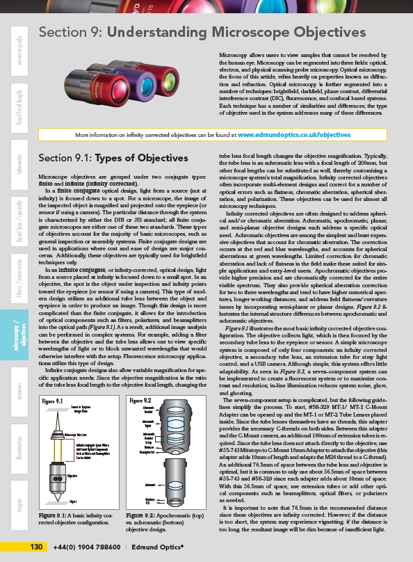
into the optical path (Figure 9.1). As a result, additional image analysis
can be performed in complex systems. For example, adding a fi lter
between the objective and the tube lens allows one to view specifi c
wavelengths of light or to block unwanted wavelengths that would
otherwise interfere with the setup. Fluorescence microscopy applications
utilize this type of design.
Infi nite conjugate designs also allow variable magnifi cation for specifi
c application needs. Since the objective magnifi cation is the ratio
of the tube lens focal length to the objective focal length, changing the
tube lens focal length changes the objective magnifi cation. Typically,
the tube lens is an achromatic lens with a focal length of 200mm, but
other focal lengths can be substituted as well, thereby customizing a
microscope system’s total magnifi cation. Infi nity corrected objectives
often incorporate multi-element designs and correct for a number of
optical errors such as fl atness, chromatic aberration, spherical aberration,
and polarization. These objectives can be used for almost all
microscopy techniques.
Infi nity corrected objectives are often designed to address spherical
and/or chromatic aberration. Achromatic, apochromatic, planar,
and semi-planar objective designs each address a specifi c optical
need. Achromatic objectives are among the simplest and least expensive
objectives that account for chromatic aberration. The correction
occurs at the red and blue wavelengths, and accounts for spherical
aberrations at green wavelengths. Limited correction for chromatic
aberration and lack of fl atness in the fi eld make these suited for simple
applications and entry-level users. Apochromatic objectives provide
higher precision and are chromatically corrected for the entire
visible spectrum. They also provide spherical aberration correction
for two to three wavelengths and tend to have higher numerical apertures,
longer working distances, and address fi eld fl atness/curvature
issues by incorporating semi-planar or planar designs. Figure 9.2 illustrates
the internal structure diff erences between apochromatic and
achromatic objectives.
Figure 9.1 illustrates the most basic infi nity corrected objective confi
guration. The objective collects light, which is then focused by the
secondary tube lens to the eyepiece or sensor. A simple microscope
system is composed of only four components: an infi nity corrected
objective, a secondary tube lens, an extension tube for stray light
control, and a USB camera. Although simple, this system off ers little
adaptability. As seen in Figure 9.3, a seven-component system can
be implemented to create a fl uorescent system or to maximize contrast
and resolution; in-line illumination reduces system noise, glare,
and ghosting.
The seven-component setup is complicated, but the following guidelines
simplify the process. To start, #58-329 MT-1/ MT-2 C-Mount
Adapter can be opened up and the MT-1 or MT-2 Tube Lenses placed
inside. Since the tube lenses themselves have no threads, this adapter
provides the necessary C-threads on both sides. Between this adapter
and the C-Mount camera, an additional 190mm of extension tubes is required.
Since the tube lens does not attach directly to the objective, use
#55-743 Mitutoyo to C-Mount 10mm Adapter to attach the objective (this
adapter adds 10mm of length and adapts the M26 thread to a C-thread).
An additional 76.5mm of space between the tube lens and objective is
optimal, but it is common to only use about 56.5mm of space between
#55-743 and #58-329 since each adapter adds about 10mm of space.
With this 56.5mm of space, use extension tubes or add other optical
components such as beamsplitters, optical fi lters, or polarizers
as needed.
It is important to note that 76.5mm is the recommended distance
since these objectives are infi nity corrected. However, if the distance
is too short, the system may experience vignetting; if the distance is
too long, the resultant image will be dim because of insuffi cient light.
Section 9.1: Types of Objectives
Object
Infinite Conjugate Space Where
Additional Optical Components
Such as Filters and Beamsplitters
Can be Added
Achromatic
Doublet
Achromat
Meniscus
PCX
Figure 9.1: A basic infi nity corrected
objective confi guration.
Figure 9.2: Apochromatic (top)
vs. achromatic (bottom)
objective design.
/objectives