/ accessories resource guide
targets illumination cameras liquid lens / specialty telecentric fixed focal length
170 +44(0) 1904 788600 | Edmund Optics® filters microscopy /
objectives
Test targets help determine the performance of an imaging system.
This includes troubleshooting a system; benchmarking, certifying,
or evaluating measurements; or establishing a foundation to ensure
multiple systems work well with one another. Because image quality
can be defined by different components, particularly resolution,
contrast, Modulation Transfer Function (MTF), Depth of Field (DOF),
or distortion, different systems may require different targets. Some
systems may require more than one. Note that the results of using a
test target are subjective if only viewed visually; using visual observation
is dependent on who is looking at the target. Someone with
20/20 vision is typically capable of discerning higher resolution or
more detail than someone with 20/25 or 20/30 vision. Additionally,
individuals that regularly look at these targets may have trained their
brains to interpolate details not actually present due to viewing the
target’s repetitive patterns. Visual inspection can help compare two
different systems but does not always validate results. It is important
to use software to truly validate measurements.
The USAF 1951 target is one of the most common test targets used
and is comprised of sets of horizontal and vertical lines, called elements,
of varying sizes (Figure 12.4). The horizontal and vertical elements
are used by a system to simultaneously test the vertical and
horizontal resolutions at discrete spatial frequencies (line pairs per
millimeter, or lp/mm) in the object plane. Each element has a unique
set of widths and spacings and is identified with a number from 1 to
6. Six sequentially numbered elements are considered a group and
each group has an identifying number that can be positive, negative,
or zero. This group number ranges from -2 to 7. The group number
and element number are then used together to determine spatial frequency.
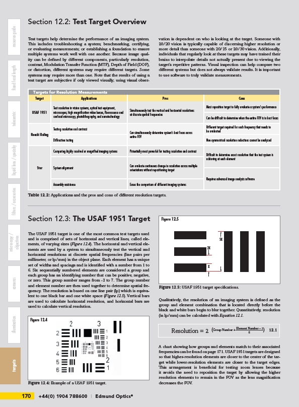
The resolution is based on one line pair (lp) which is equivalent
to one black bar and one white space (Figure 12.5). Vertical bars
are used to calculate horizontal resolution, and horizontal bars are
used to calculate vertical resolution.
Figure 12.5
Qualitatively, the resolution of an imaging system is defined as the
group and element combination that is located directly before the
black and white bars begin to blur together. Quantitatively, resolution
(in lp/mm) can be calculated with Equation 12.1.
A chart showing how groups and elements match to their associated
frequencies can be found on page 171. USAF 1951 targets are designed
so that higher-resolution elements are closer to the center of the target
while lower-resolution elements are closer to the target edges.
This arrangement is beneficial for testing zoom lenses because
it avoids the need to reposition the target by allowing the higher
resolution elements to remain in the FOV as the lens magnification
decreases the FOV.
Section 12.2: Test Target Overview
Targets for Resolution Measurements
Target Applications Pros Cons
USAF 1951
Test resolution in vision systems, optical test equipment,
microscopes, high magnification video lenses, fluorescence and
confocal microscopy, photolithography, and nanotechnology
Simultaneously test the vertical and horizontal resolutions
at discrete spatial frequencies
Must reposition target to fully evaluate a system’s performance
Can be difficult to determine when the entire FOV is in best focus
Ronchi Ruling
Testing resolution and contrast
Can simultaneously determine system’s best focus across
entire FOV
Different target required for each frequency that needs to
be evaluated
Diffraction testing Non-symmetrical resolution reductions cannot be analyzed
Star
Comparing highly resolved or magnified imaging systems Potentially most powerful for testing resolution and contrast
Difficult to determine exact resolution that the test system is
achieving at each element
System alignment Can evaluate continuous change in resolution across multiple
orientations without repositioning target
Requires advanced image analysis software
Assembly assistance Eases the comparison of different imaging systems
Table 12.2: Applications and the pros and cons of different resolution targets.
Section 12.3: The USAF 1951 Target
Figure 12.4
Figure 12.4: Example of a USAF 1951 target.
5X
2X
X
Figure 12.5: USAF 1951 target specifications.
Resolution = 2 (Group Number + Element Number – 1) 6 12.1