Telecentric Lens
Specular Object
Telecentric Lens
www.edmundoptics.co.uk/imaging 159
resource guide fixed focal length telecentric liquid lens / specialty filters/accessories
cameras illumination targets
microscopy /
objectives
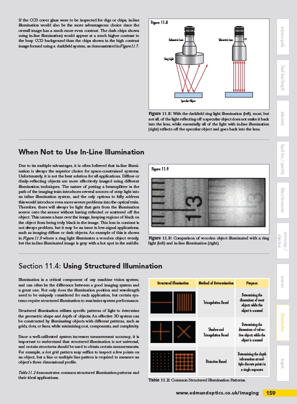
Figure 11.8
Figure 11.9
If the CCD cover glass were to be inspected for digs or chips, in-line
illumination would also be the more advantageous choice since the
overall image has a much more even contrast. The dark chips shown
using in-line illumination) would appear at a much higher contrast to
the busy CCD background than the chips shown in the high contrast
image formed using a darkfield system, as demonstrated in Figure 11.7.
Section 11.4: Using Structured Illumination
Illumination is a critical component of any machine vision system,
and can often be the difference between a good imaging system and
a great one. Not only does the illumination position and wavelength
need to be uniquely considered for each application, but certain systems
require structured illumination to maximize system performance.
Structured illumination utilizes specific patterns of light to determine
the geometric shape and depth of objects. An effective 3D system can
be constructed by illuminating objects with different patterns, such as
grids, dots, or lines, while minimizing cost, components, and complexity.
Since a well-calibrated system increases measurement accuracy, it is
important to understand that structured illumination is not universal,
and certain structures should be used to obtain certain measurements.
For example, a dot grid pattern may suffice to inspect a few points on
an object, but a line or multiple line pattern is required to measure an
object’s three dimensional profile.
Table 11.2 demonstrates common structured illumination patterns and
their ideal applications.
Ring Light
Figure 11.8: With the darkfield ring light illumination (left), most, but
not all, of the light reflecting off a specular object does not make it back
into the lens, while essentially all of the light with in-line illumination
(right) reflects off the specular object and goes back into the lens.
When Not to Use In-Line Illumination
Figure 11.9: Comparison of wooden object illuminated with a ring
light (left) and in-line illumination (right).
Due to its multiple advantages, it is often believed that in-line illumination
is always the superior choice for space-constrained systems.
Unfortunately, it is not the best solution for all applications. Diffuse or
dimly-reflecting objects are more effectively imaged using different
illumination techniques. The nature of putting a beamsplitter in the
path of the imaging train introduces several sources of stray light into
an inline illumination system, and the only options to fully address
this would introduce even more severe problems into the optical train.
Therefore, there will always be light that gets from the illumination
source onto the sensor without having reflected or scattered off the
object. This causes a haze over the image, keeping regions of black on
the object from being truly black in the image. This loss in contrast is
not always problem, but it may be an issue in low-signal applications,
such as imaging diffuse or dark objects. An example of this is shown
in Figure 11.9 where a ring light illuminates a wooden object evenly,
but the in-line illuminated image is grey with a hot spot in the middle.
Structured Illumination Method of Determination Purpose
Triangulation Based
Determining the
dimensions of most
objects while the
object is scanned
Shadow and
Triangulation Based
Determining the
dimensions of refractive
objects while the
object is scanned
Distortion Based
Determining the depth
information at multiple
discrete points in
a single exposure
Table 11.2: Common Structured Illumination Patterns.
/imaging