resource guide fixed focal length telecentric liquid lens / specialty filters / accessories microscopy / objectives cameras illumination targets
Bandpass Filter Transmission
Section 8.2: Applications with Machine Vision Filtering
www.edmundoptics.co.uk/imaging 125
T (%)
80
60
40
20
0
490 495 500 505 510 515
(nm)
15°AOI
0° AOI
Thin Film
Layers
45°
Substrate
2x x
Figure 3a
Figure 3b
Shortpass Filter
Longpass Filter
Transmission
Wavelength
Figure 2a
Figure 2b
Notch Filter
Bandpass Filter
Transmission
Wavelength
When designing a machine vision system, it is important to enhance
the contrast of the inspected object’s features of interest. For an introduction
to contrast, see Section 2.3. Filtering provides a simple way to
enhance the contrast of the image while blocking out unwanted illumination.
There are many different ways filters can enhance contrast,
and the filter type is dependent on the application. Some common
filters used in machine vision are colored glass, interference, Neutral
Density (ND), and polarization.
Colored glass bandpass filters are some of the simplest filters available
for drastically improving image quality. These filters work incredibly
well at narrowing the waveband that is visible by the vision system,
and are often less expensive than comparable interference filters.
Colored glass filters work best when used to block out colors on the
opposite side of the color wheel (Figure 4).
Figure 4: Color wheel demonstrating that warm colors should be
used to filter out cool colors on the opposite side of the wheel.
(Continued from page 124)
Shortpass filters are the opposite, passing shorter wavelengths and
blocking long. Bandpass filters pass a band of wavelengths, while
blocking longer and shorter wavelengths that lie outside the passband.
The inverse of a bandpass filter is a notch filter, which blocks a
band of wavelengths and passes the longer and shorter. Transmission
curve shapes for these filter types are shown in Figure 2.
Filters designed for deep blocking (high Optical Density) and steep
slopes (sharp transition from blocking to transmission) are used in applications
where precise light control is critical. Most machine vision
applications do not require this level of precision; typically, any filter
with an Optical Density (OD) of 4 or greater is more precise than
required and adds unnecessary cost.
Because hard coated filters utilize optical interference to achieve
such precise transmission and rejection bands, they introduce difficulties
when used in machine vision applications. All interference
filters are designed for a specific Angle of Incidence (AOI), generally
0° unless specifically designated otherwise. When used in machine
vision, these filters are generally placed in front of the lens; doing
such causes the filter to accept light coming from angles dictated by
the angular field of view (AFOV) of the lens. Especially in the case
of short focal length (large AFOV) lenses, the light that is transmitted
through the filter will often display an unwanted effect known as blue
shift. For example, a wide angle 4.5mm focal length lens will have a
much larger blue shift than a narrow angle 50mm focal length lens.
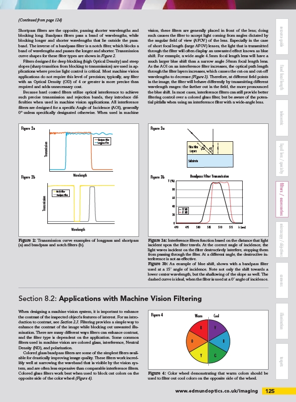
As the AOI on an interference filter increases, the optical path length
through the filter layers increases, which causes the cut-on and cut-off
wavelengths to decrease (Figure 3). Therefore, at different field points
in the image, the filter will behave differently by transmitting different
wavelength ranges: the farther out in the field, the more pronounced
the blue shift. In most cases, interference filters can still provide better
filtering control over a colored glass filter, but be aware of the potential
pitfalls when using an interference filter with a wide-angle lens.
Figure 3a: Interference filters function based on the distance that light
incident upon the filter travels. At the correct angle of incidence, the
light waves incident on the filter destructively interfere, stopping them
from passing through the filter. At a different angle, the destructive interference
is not as effective.
Figure 3b: An example of blue shift, shown with a bandpass filter
used at a 15˚ angle of incidence. Note not only the shift towards a
lower center wavelength, but the shallowing of the slope as well. The
dashed curve is ideal, when the filter is used at a 0˚ angle of incidence.
Figure 2: Transmission curve examples of longpass and shortpass
(a) and bandpass and notch filters (b).
Warm Cool
R V
O
Y
B
G
Figure 4
/imaging