cameras filters / accessories resource guide
illumination liquid lens / specialty telecentric fixed focal length
microscopy /
objectives
Section 11.5:
Telecentric Illumination: Importance
in Machine Vision Applications
Imaging and inspection projects require precision optical components
and alignment to achieve optimal performance. These machine vision
inspection applications utilize imaging lenses, illumination sources, cameras,
and mechanics, to name a few key components. The choice of imaging
lens and camera is integral to the success of an application; however,
illumination plays a very important role as well. One of the most
precise types of illumination geometry is telecentric illumination. What is
telecentric illumination? How can it help achieve better results compared
to standard backlight illumination? To answer these questions, consider
illumination theory, benefits, and a real-world inspection application.
Telecentric Illumination Theory
In optics, telecentricity is a unique property of certain multi-element
lens designs in which the chief rays are collimated and parallel to the
optical axis in image and object space. This results in constant magnification
regardless of image or object location, a key characteristic of
telecentricity. Telecentricity is classified in three ways: object-space,
image-space, and double. For additional information and definitions,
see Section 4 on pages 29-33.
In illumination, the concept in which light rays are collimated and
parallel to the optical axis applies as well. This is the case with a telecentric
illuminator. Telecentric illuminators use optics to direct light
from a fiber optic light guide or LED onto an object under inspection,
producing a high contrast silhouette. A telecentric illuminator increases
edge contrast and measurement accuracy by decreasing diffuse
reflections from the object. Collimated light rays exit the illuminator
and remain collimated as they strike an object’s surface (Figure 11.10).
In contrast, light rays from a standard backlight expand and interfere
with one another, producing diffuse reflections (Figure 11.10).
How Does Telecentric Illumination Create a High
Contrast Silhouette?
Telecentric illuminators work by employing high-quality glass optical
lenses to collimate light from a fiber optic light guide or LED spotlight.
Divergent light from the source enters the glass assembly, becoming
parallel and therefore highly concentrated as it exists. Nearly all light
that enters the telecentric illuminator (neglecting back reflection and absorption
through each optical lens) strikes the object under inspection.
Pros and Cons of Telecentric Illumination
Telecentric illumination is ideal for precision measurements where
accuracy, repeatability, and throughput are key factors in an application’s
success. To achieve the best results, consider these eight key
benefits of telecentric illumination:
1. Superior detection of small defects
2. Increased measurement accuracy and repeatability compared
to standard backlight illumination
3. Elimination of blurred edges caused by diffuse reflections
4. Increased light intensity from collimated light rays
5. High contrast images from elimination of blurred edges and increased
light intensity
160 +44(0) 1904 788600 | Edmund Optics® targets 6. Reduced camera exposure times from increased light intensity
7. Faster systems and higher throughput compared to standard
backlight illumination
8. Increased distance between object and illumination source
However, telecentric illuminators may have some drawbacks, such
as being space consuming and sometimes costly. Larger objects will
require larger telecentric illuminators. For applications where space
or cost is a concern, a collimated backlight may be a better option.
Collimated backlights are a standard backlight with an integrated film
to collimate light. Although they do not perform as well as a telecentric
illuminators, collimated backlights are less diffuse than standard
backlights and thereby eliminate some of the blurred edges caused
by diffuse reflections.
Application Example
While understanding the theoretical framework of telecentric illumination
is a great first step, analyzing a real-world application of this
precision illumination geometry will reinforce why it is needed in machine
vision applications.
One example includes the measurement and inspection of thread diameters
on a stainless steel post. The small size of the objects under
inspection (10mm), and the need to measure thread pitch, prohibits visual
sorting. The original system employed for this application included
a standard LED backlight in front of a 0.6X TECHSPEC® SilverTL™ Telecentric
Lens (#56-678) on a 640 x 480 pixel CCD camera. A picking
robot moved parts from the manufacturing turntable to the vision system
for image acquisition. A second picking robot then used the collected
information from the acquisition to designate parts into pass or fail bins.
Although well-designed, the standard backlight system could not
inspect parts smaller than 10mm and was limited to 10ppm, whereas
40ppm was required to keep up with new production flow. In addition,
the low light intensity produced from the diffuse LED backlight necessitated
a 2.5ms camera exposure time; new production-line speeds allowed
only 800μsec for blur free image capture. One simple fix was to
increase the camera’s gain setting to decrease exposure time. However,
this increased the signal-to-noise ratio in the system and decreased
measurement accuracy. The answer became clear – telecentric illumination!
By replacing the diffuse LED backlight with a TECHSPEC®
Telecentric Backlight Illuminator (#62-760), the intensity of the light
striking the threads increased, reducing the camera’s exposure time
and increased overall image contrast by reducing diffuse reflections.
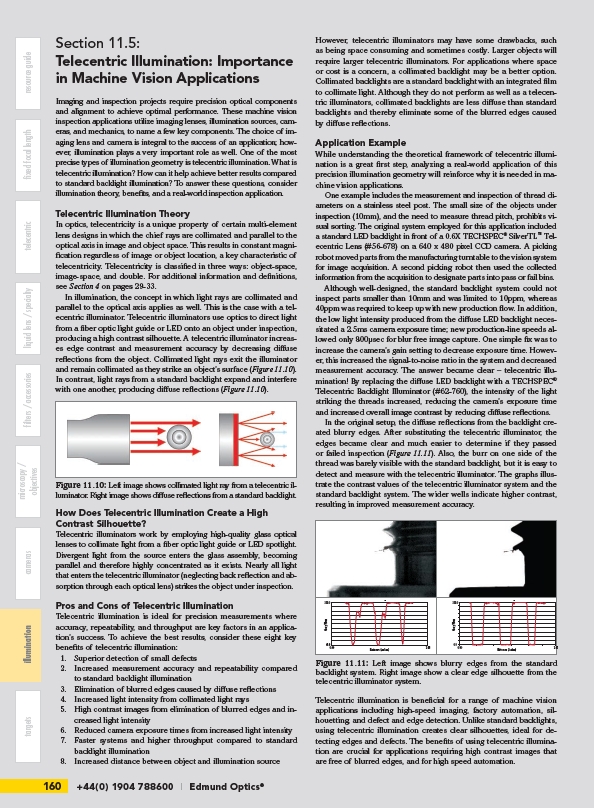
In the original setup, the diffuse reflections from the backlight created
blurry edges. After substituting the telecentric illuminator, the
edges became clear and much easier to determine if they passed
or failed inspection (Figure 11.11). Also, the burr on one side of the
thread was barely visible with the standard backlight, but it is easy to
detect and measure with the telecentric illuminator. The graphs illustrate
the contrast values of the telecentric illuminator system and the
standard backlight system. The wider wells indicate higher contrast,
resulting in improved measurement accuracy.
Standard Backlight
255.0
Gray Value
40.0
0.00 Distamce (inches) 2.98
Telecentric Backlight
255.0
Gray Value
0.0
0.00 Distamce (inches) 2.95
Standard Backlight
255.0
Gray Value
40.0
0.00 Distamce (inches) 2.98
255.0
Telecentric illumination is beneficial for a range of machine vision
applications including high-speed imaging, factory automation, silhouetting,
and defect and edge detection. Unlike standard backlights,
using telecentric illumination creates clear silhouettes, ideal for detecting
edges and defects. The benefits of using telecentric illumination
are crucial for applications requiring high contrast images that
are free of blurred edges, and for high speed automation.
Figure 11.10: Left image shows collimated light ray from a telecentric illuminator.
Right image shows diffuse reflections from a standard backlight.
Figure 11.11:Telecentric Left Backlight
image shows blurry edges from the standard
backlight system. Right image show a clear edge silhouette from the
telecentric illuminator system.
0.0
0.00 Distamce (inches) 2.95
Gray Value