Monotonic Distortion vs. Image Height
Wavelength:
Non-Monotonic Distortion vs. Image Height
Telecentricity Plot for a Typical Telecentric Lens
486nm
588nm
656nm
Wavelength:
-0.100 0.000 0.100
Figure 4.7: Telecentricity plot for a typical Telecentric Lens
www.edmundoptics.co.uk/imaging 31
introduction fundamentals lens specifications real world performance telecentricity lens mechanics lens selection guide
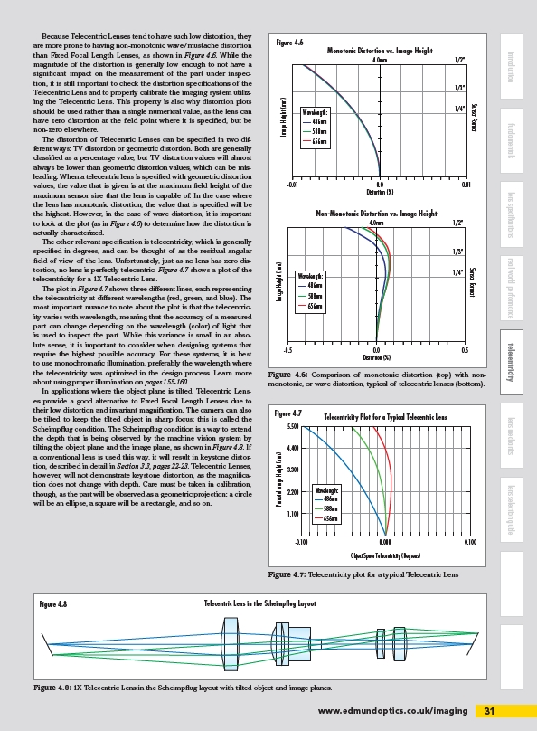
Because Telecentric Lenses tend to have such low distortion, they
are more prone to having non-monotonic wave/mustache distortion
than Fixed Focal Length Lenses, as shown in Figure 4.6. While the
magnitude of the distortion is generally low enough to not have a
significant impact on the measurement of the part under inspection,
it is still important to check the distortion specifications of the
Telecentric Lens and to properly calibrate the imaging system utilizing
the Telecentric Lens. This property is also why distortion plots
should be used rather than a single numerical value, as the lens can
have zero distortion at the field point where it is specified, but be
non-zero elsewhere.
The distortion of Telecentric Lenses can be specified in two different
ways: TV distortion or geometric distortion. Both are generally
classified as a percentage value, but TV distortion values will almost
always be lower than geometric distortion values, which can be misleading.
When a telecentric lens is specified with geometric distortion
values, the value that is given is at the maximum field height of the
maximum sensor size that the lens is capable of. In the case where
the lens has monotonic distortion, the value that is specified will be
the highest. However, in the case of wave distortion, it is important
to look at the plot (as in Figure 4.6) to determine how the distortion is
actually characterized.
The other relevant specification is telecentricity, which is generally
specified in degrees, and can be thought of as the residual angular
field of view of the lens. Unfortunately, just as no lens has zero distortion,
no lens is perfectly telecentric. Figure 4.7 shows a plot of the
telecentricity for a 1X Telecentric Lens.
The plot in Figure 4.7 shows three different lines, each representing
the telecentricity at different wavelengths (red, green, and blue). The
most important nuance to note about the plot is that the telecentricity
varies with wavelength, meaning that the accuracy of a measured
part can change depending on the wavelength (color) of light that
is used to inspect the part. While this variance is small in an absolute
sense, it is important to consider when designing systems that
require the highest possible accuracy. For these systems, it is best
to use monochromatic illumination, preferably the wavelength where
the telecentricity was optimized in the design process. Learn more
about using proper illumination on pages 155-160.
In applications where the object plane is tilted, Telecentric Lenses
provide a good alternative to Fixed Focal Length Lenses due to
their low distortion and invariant magnification. The camera can also
be tilted to keep the tilted object in sharp focus; this is called the
Scheimpflug condition. The Scheimpflug condition is a way to extend
the depth that is being observed by the machine vision system by
tilting the object plane and the image plane, as shown in Figure 4.8. If
a conventional lens is used this way, it will result in keystone distortion,
described in detail in Section 3.3, pages 22-23. Telecentric Lenses,
however, will not demonstrate keystone distortion, as the magnification
does not change with depth. Care must be taken in calibration,
though, as the part will be observed as a geometric projection: a circle
will be an ellipse, a square will be a rectangle, and so on.
Figure 4.8
Figure 4.8: 1X Telecentric Lens in the Scheimpflug layout with tilted object and image planes.
Object Space Telecentricity (Degrees)
Paraxial Image Height (mm)
5.500
4.400
3.300
2.200
1.100
486nm
588nm
656nm
Figure 4.7
Telecentric Lens in the Scheimpflug Layout
Distortion (%)
Image Height (mm)
1/2”
1/3”
1/4”
-0.5 0.0
0.5
Sensor Format
4.0mm
Wavelength:
Distortion (%)
Image Height (mm)
1/2”
1/3”
1/4”
-0.01 0.0
0.01
Sensor Format
4.0mm
486nm
588nm
656nm
Figure 4.6: Comparison of monotonic distortion (top) with nonmonotonic,
or wave distortion, typical of telecentric lenses (bottom).
Figure 4.6
/imaging