illumination cameras microscopy / objectives filters / accessories liquid lens / specialty telecentric fixed focal length resource guide
Section 5: Lens Mechanics
There are many ways to interface a lens to a camera. Lenses and cameras
have several standard mount types that feature either threads
or a bayonet-type mount. A lens needs to not only be mechanically
compatible with the mount type; it also must have the same flange
distance as the camera. Flange distance or flange focal distance is the
distance from the mounting shoulder to the image plane.
C-Mount
The C-Mount standard is one of the most common lens mount types
in machine vision. The C-Mount standard features a thread 1” in diameter
with 32 threads per inch (TPI). The C-Mount flange distance is
17.526mm. It is ideal for many industrial applications, as the threaded
mount provides a robust, controlled interface between the camera
and lens.
The CS-Mount standard is the same as the C-Mount standard, but
with a reduced flange distance of 12.526mm. A CS-Mount camera
can be modified to accommodate C-Mount lenses with the use of
a 5mm extension tube between the lens and camera. A CS-Mount
lens may appear to be compatible with a C-mount camera because it
will thread onto it. However, a CS-Mount lens cannot be used with a
C-Mount camera because the lens will focus the image at a location
inside the flange and in front of the sensor.
F-Mount
The F-Mount standard is a bayonet-style mount common with line
scan cameras and large format cameras. It was developed by Nikon
and is used on 35mm (43.3mm) SLR photography cameras. The FMount
standard features a diameter of 44mm and a flange distance
of 46.5mm. The spring loaded bayonet connection provides ease of
use for photographers but can contribute to camera-lens misalignment
in industrial applications.
Applications can require a lens to stretch beyond its limits or be precisely
dialed-in to its ideal design parameters. Lens spacers, shims,
and focal length extenders are simple tools a user can easily use to
achieve these requirements. These tools are used in between the lens
and lens mount on the camera. Spacers and focal length extenders
modify field of view (FOV) or working distance (WD) in fixed focal
length lenses, whereas shims can be used to precisely control the WD
of telecentric lenses.
Lens Spacers
Most fixed focal length lenses have integrated mechanics to focus at
different WDs. The fixed focal length nature of the design means that
the elements move throughout a defined range (and do not move relative
to one another), which dictates the WDs where focus is achievable.
This predefined range is chosen based on the design of the lens.
However, it is often advantageous to stretch a lens beyond its limits
to fit an application where smaller FOVs or shorter WDs are required.
Augmenting the system with a spacer between the camera and lens
changes the range of WDs over which the lens performs optimally.
34 +44(0) 1904 788600 | Edmund Optics® targets The main purpose of adding a spacer is to increase the vision
system’s magnification or shorten the WD; these two changes occur
in tandem and are explained by the Gaussian imaging equations.
TFL-Mount
The TFL-Mount was designed for use with APS-C (27.9mm) sensors
that are much too large for use with a C-Mount, but are still too small
for an F-Mount. This mount can be thought of as a larger C-Mount;
it has thread dimensions of M35x0.75mm, and the same flange distance
as the C-Mount: 17.526mm. The TFL-Mount provides the same
robustness as the C-Mount but for larger sized sensors, without the
drawbacks of the F-Mount.
S-Mount (M12)
The S-Mount is a common mount in surveillance CCTV cameras and
board-level cameras and is used with M12 lenses. This smaller mount
type has a metric thread and pitch of M12 x 0.5 and no standardized
flange distance.
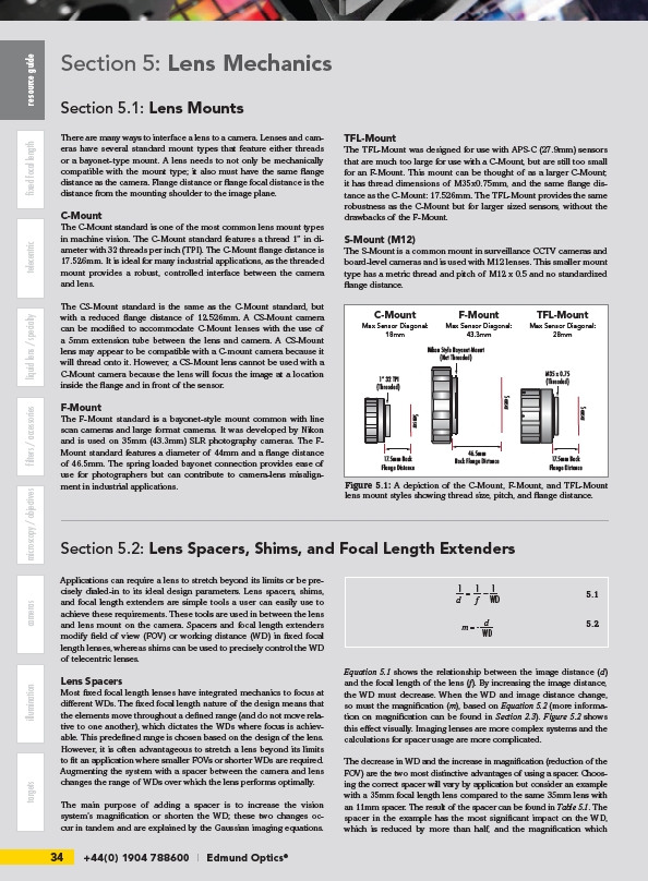
Figure 5.1: A depiction of the C-Mount, F-Mount, and TFL-Mount
lens mount styles showing thread size, pitch, and flange distance.
1
Equation 5.1 shows the relationship between the image distance (d)
and the focal length of the lens (f). By increasing the image distance,
the WD must decrease. When the WD and image distance change,
so must the magnification (m), based on Equation 5.2 (more information
on magnification can be found in Section 2.3). Figure 5.2 shows
this effect visually. Imaging lenses are more complex systems and the
calculations for spacer usage are more complicated.
The decrease in WD and the increase in magnification (reduction of the
FOV) are the two most distinctive advantages of using a spacer. Choosing
the correct spacer will vary by application but consider an example
with a 35mm focal length lens compared to the same 35mm lens with
an 11mm spacer. The result of the spacer can be found in Table 5.1. The
spacer in the example has the most significant impact on the WD,
which is reduced by more than half, and the magnification which
Section 5.1: Lens Mounts
Section 5.2: Lens Spacers, Shims, and Focal Length Extenders
1
=
1
–
d f WD
d m = -
WD
5.1
5.2
1” 32 TPI
(Threaded)
Nikon Style Bayonet Mount
(Not Threaded)
17.5mm Back
Flange Distance Sensor
Sensor
46.5mm
Back Flange Distance
M35 x 0.75
(Threaded)
Sensor
17.5mm Back
Flange Distance
C-Mount
Max Sensor Diagonal:
18mm
F-Mount
Max Sensor Diagonal:
43.3mm
TFL-Mount
Max Sensor Diagonal:
28mm