Section 11.1: Brightfield and Darkfield Illumination in Machine Vision
Figure 11.1 Figure 11.2 Figure 11.3 Figure 11.4
www.edmundoptics.co.uk/imaging 155
resource guide fixed focal length telecentric liquid lens / specialty filters/accessories
cameras illumination targets
microscopy /
objectives
Section 11: Illumination
Brightfield and darkfield illumination are terms that come from microscopy,
but the principles behind them are applied to machine vision as
well. The different uses of the terms can be confusing, but an understanding
of them will aid in understanding the different illumination
techniques for machine vision applications.
Brightfield Illumination
In brightfield illumination, the light source is in the field of view of the
imaging system. In the traditional microscopy definition, in which the
object is transparent and the illumination is coming from behind the
object, the light source is directly in line with the objective and the cone
of illumination within its field of view. In Figure 11.1, the blue triangles
represent the field of view of the objective and the red rays from the
illumination are within this area.
In machine vision, the illumination is less likely to come from directly
behind the object than in microscopy. For this reason, brightfield illumination
for machine vision involves light reflected from an object that
enters the lens. Figure 11.2 shows this concept, in which a specular (or
mirror-like) object is assumed, where the law of reflection dictates that
the angle of reflection will equal the angle of incidence.
Figure 11.2 shows the marginal field rays that define the edges of the cone
of light that comes into the lens over its entire field in blue; these are the
same rays as in Figure 11.1. If the rays are allowed to hit the object and
reflect back up to form a “W” shape, as in Figure 11.2, the light originating
from within the “W” will reflect into the lens and be classified as brightfield
illumination. This reflection makes specular objects in the field of
view appear bright. Diffuse objects will scatter the light, causing less light
to make it back into the lens and making them appear darker.
Darkfield Illumination
In contrast to brightfield illumination, darkfield illumination occurs
when the light source originates from outside the field of view of the
lens, causing undeviated light from the illumination source to not make
it into the lens.
In traditional darkfield microscopy, shown in Figure 11.3, the light
source is moved to outside the blue cone representing the objective’s
field of view. This causes the background to be dark, but any translucent
object will scatter the illumination, causing some light to go into
the lens. This results in the translucent object becoming brighter.
In machine vision, darkfield illumination occurs when the light reflected
off specular objects does not make it into the lens. Using the same “W” to
represent the lens’ field of view used above for brightfield illumination, the
light source is moved outside the “W” in machine vision darkfield illumination.
This causes diffuse objects to scatter light into the lens, while specular
objects remain dark because the reflected light from the illumination
source will reflect away from the camera, as seen in Figure 11.4.
How Important Is Illumination?
Customers often struggle with contrast and resolution problems in an
imaging system, while underestimating the power of proper illumination.
In fact, desired image quality can often be met by improving
a system’s illumination rather than by investing in higher resolution
detectors, imaging lenses, and software.
Correct illumination is critical to an imaging system and improper
illumination can cause a variety of image problems. Blooming or hot
spots, for example, can hide important image information, as can
shadowing. In addition, shadowing can also cause false edge calculations
when measuring, resulting in inaccurate measurements. Poor
illumination can also result in a low signal-to-noise ratio. Non-uniform
lighting, in particular, can harm signal-to-noise ratios and make tasks
such as thresholding more difficult. These are only a few of the reasons
why correct illumination for your application is so important.
To ensure optimal illumination when integrating a system, it is important
to recognize the role that the right components play. Every component
affects the amount of light incident on the sensor and, therefore, the system’s
image quality. The imaging lens’ aperture (f/#) impacts the amount
of light incident on the camera. Illumination should be increased as the
lens aperture is closed (i.e., higher f/#). High power lenses usually require
more illumination, as smaller areas viewed reflect less light back into the
lens. The camera’s minimum sensitivity is also important in determining
the minimum amount of light required in the system. In addition, camera
settings such as gain, shutter speed, etc., affect the sensor’s sensitivity.
Illumination
Object
Objective
Illumination
Machine Vision Lens
Object
Illumination
Object
Objective
Object
Illumination
Machine Vision Lens
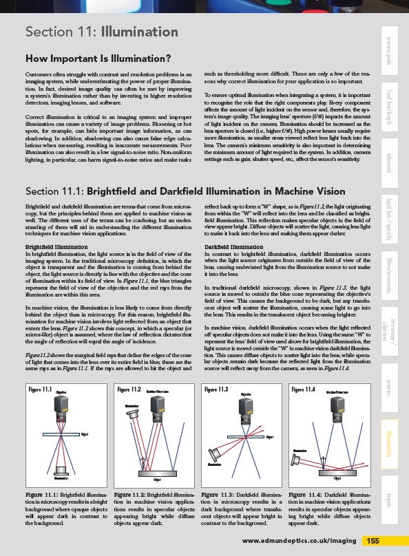
Figure 11.1: Brightfield illumination
in microscopy results in a bright
background where opaque objects
will appear dark in contrast to
the background.
Figure 11.2: Brightfield illumination
in machine vision applications
results in specular objects
appearing bright while diffuse
objects appear dark.
Figure 11.3: Darkfield illumination
in microscopy results in a
dark background where translucent
objects will appear bright in
contrast to the background.
Figure 11.4: Darkfield illumination
in machine vision applications
results in specular objects appearing
bright while diffuse objects
appear dark.
/imaging