Lens Selection, Small Sensors Lens Selection,400
Working Distance (mm)
742.5
594
445.5
297
148.5
0
Horizontal FOV (mm, ." Sensor)
875
Lens Selection, Small Sensors Lens Selection, Medium Format Sensors
1595
0 100 200 300 400 500 600 700 800 900 1000
www.edmundoptics.co.uk/imaging 39
resource guide telecentric liquid lens/specialty objectives cameras illumination targets
fixed focal length filters/accessories microscopy /
points meet on the coordinate plane. The closest lens to the intersecting
points describes the best starting point of investigation for which
lens to use and considerably narrows the large fi eld of lenses from
which to choose.
Additionally, these plots also illustrate several important points about
Fixed Focal Length lenses in machine vision. First, longer focal length
lenses have longer minimum WDs, which is a consequence of their
optical designs. Minimum WD can be shortened by adding spacers
between the lens and camera, but image quality will eventually suffer
(see Section 5.2, Lens Spacers, Shims and Focal Length Extenders on
pages 34-35 for more information). Second, larger sensors provide a
larger FOV with the same focal length lens. For example, at a WD of
350mm, a 12mm lens on a 2/3 ” sensor will have a FOV of about 370mm,
but on a 1” sensor at the same WD, the FOV is approximately 530mm
- an increase of 43%. Lastly, there are gaps in the plots, indicative that
a standard off -the-shelf Fixed Focal Length Lens does not exist. For
example, it is impossible to achieve a 525mm FOV at a 600mm with
a 2/3 ” sensor with available focal lengths. The closest lens that exists is
an 8.5mm focal length, which would need to be used at a WD of about
510mm to achieve that FOV.
These plots should only be used as the fi rst step in narrowing down
which lens is the best for an application. They do not answer questions
about image quality, distortion, relative illumination, or any other important
qualities of an imaging lens; they merely address FOV relative
to sensor size.
How to Choose a Fixed Magnifi cation Lens
At fi rst glance, lenses such as Telecentrics or microscope objectives
can seem intimidating to specify into an imaging system as they do not
behave the same way as traditional Fixed Focal Length Lenses. However,
the selection process is actually much more straightforward than
a traditional lens.
With a few exceptions,500
Fixed Magnifi cation Lenses generally only
function properly at a single WD. They are also specifi ed by their magnifi
742.5
cation, such as a 2.0X Telecentric Lens. Because the magnifi cations
are physically listed on the lenses, that is where they always work, and
their FOV can by described simply by rearranging Equation 1.1 from
Section 1.2: Imaging Fundamentals to:
H
m
where m is the magnifi cation specifi ed for the lens and H is the sensor
size. This equation shows that regardless of the sensor size, the magnifi
cation will remain the same; only the FOV changes.
500
300
200
100
0
Horizontal FOV (mm, " Sensor)
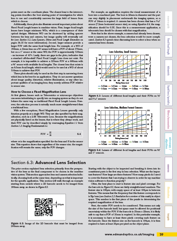
Figure 6.3: Lenses of diff erent focal lengths and their FOVs on ⅓ ”
and 1⁄1.8” sensors
700
525
350
175
0
Horizontal FOV (mm, " Sensor) 0 100 200 300 400 500 600 700 800 900 1000
0 100 200 300 f=3.5mm
f=4.5mm
f=6mm
f=8.5mm
f=12mm
f=6mm
f=f=16mm
f=25mm
f=35mm
f=50mm
f=100mm
f=35mm
f=875
Figure 6.4: Lenses of diff erent focal lengths and their FOVs on 2/3 ”
and 1” sensors.
Working Distance (mm)
400
300
200
100
0
1276
957
638
319
0
Horizontal FOV (mm, " Sensor)
Horizontal FOV (mm, 1" Sensor)
594
445.5
297
148.5
0
Horizontal FOV (mm, ." Sensor)
700
525
350
175
0
Horizontal FOV (mm, " Sensor)
0 100 200 300 400 500 600 700 800 900 1000
Working Distance (mm)
f=3.5mm
f=16mm
f=4.5mm
f=25mm
f=6mm
f=35mm
f=8.5mm
f=50mm
f=12mm
f=100mm
f=6mm
f=35mm
f=8.5mm
f=50mm
f=12mm
f=100mm
f=16mm f=25mm
FOV = 6.4
Section 6.3: Advanced Lens Selection
For example, an application requires the visual measurement of a
bore into a machined part. The bore is 20mm in diameter and the part
can vary slightly in placement underneath the imaging system, so a
FOV of 24mm is required. A camera has been chosen that has a 1⁄1.8”
sensor (7.2mm horizontal sensor size), so using Equation 6.4, the magnifi
cation should be 0.3X. Since this is a measurement application, a
telecentric lens should be chosen with that magnifi cation.
Note that in the above example, a camera had already been chosen;
were a camera not chosen, the lens selection would be more complicated.
Section 6.3 spends time discussing how to select a lens when no
camera has been chosen.
The prior section explained lens selection primarily from the perspective
of the lens as the fi nal component to be chosen in the machine
vision system. This section approaches lens and camera selection holistically,
choosing both at the same time, depending on what is important
for the specifi c application. This section will walk through an example
starting from scratch where a 2D barcode needs to be imaged from
200mm away, as shown in Figure 6.5.
100μm
Figure 6.5: Image of the 2D barcode that must be imaged from
200mm away.
Starting with the object to be inspected and breaking it down into its
constituent parts is the fi rst step in lens selection. What are the important
features? How large are these features? How many pixels do I need
to cover the feature that I am trying to observe in order for my machine
vision software to function properly?
Often, the best place to start is feature size and pixel coverage. For
the barcode in Figure 6.5, these are fairly straightforward numbers. The
feature size is 100μm, with empty space of at least 100μm in between
features. This means that the frequency that this feature corresponds to
is 5lp/mm (see Section 2.2: Resolution for a review of this math) in object
space. This number is the fi rst piece of the puzzle in determining the
required magnifi cation of the lens.
Next, the entire FOV needs to be considered. This means not only
the size of the barcode itself, but space must be allowed for positional
uncertainty within the FOV. If the barcode is 25mm x 25mm, it is likely
safe to say that a FOV of 35mm is required. In this particular example,
it is necessary to have at least three pixels covering each feature on
the barcode. Since the feature size on the barcode is 100μm, it is then
required to have at least 33μm per pixel on the object plane.
/imaging