AFOV/2
www.edmundoptics.eu/imaging 9
introduction fundamentals lens specifications real world performance telecentricity lens mechanics lens selection guide
The 14.25° derived in Example 1 (see white box below) can be used
to determine the lens that is needed, but the sensor size must also be
chosen. Changing the sensor size changes how much of the lens’s image
will be utilized; this alters the AFOV of the system and thus the overall
FOV. The larger the sensor, the larger the obtainable AFOV for the same
focal length. For example, a 25 mm lens could be used with a ½” (6.4mm
horizontal) sensor or a 35 mm lens could be used with a 2/3” (8.8 mm horizontal)
sensor as they would both approximately produce a 14.5° AFOV
on their respective sensors.
Alternatively if the sensor has already been chosen, the focal
length can be determined directly from the FOV and WD by substituting
Equation 1.2 in Equation 1.3, as shown in Equation 1.4,
f = (H × WD)
FOV
As previously stated, some amount of flexibility to the system’s WD
should be factored in, as the above examples are only first-order approximations
and do not take distortion into account.
1.4
Calculating FOV Using a Lens with a Fixed Magnification
Generally, lenses that have fixed magnifications have fixed or limited
WD ranges. While using a telecentric or other fixed magnification lens
can be more constraining, as they do not allow for different FOVs by
varying the WD, the calculations for them are very direct, as shown
in Equation 1.5.
FOV = H
m
Since the desired FOV and sensor are often known, the lens selection
process can be simplified by using Equation 1.1.
m = H
FOV
1.1
If the required magnification is already known and the WD is constrained,
Equation 1.4 can be rearranged (replacing H÷FOV with magnification)
and used to determine an appropriate fixed focal length
lens, as shown in Equation 1.6.
m = f
WD
Be aware that Equation 1.6 is an approximation and will rapidly deteriorate
for magnifications greater than 0.1 or for short WDs. For magnifications
beyond 0.1, either a fixed magnification lens or computer
simulations (e.g. Zemax) with the appropriate lens model should be
used. For the same reasons, lens calculators commonly found on the
internet should only be used for reference. When in doubt, consult a
lens specification table.
Note: Horizontal FOV is typically used in discussions of FOV as a
matter of convenience, but the sensor aspect ratio (ratio of a sensor’s
width to its height) must be taken into account to ensure that the entire
object fits into the image. The aspect ratio is the fraction (e.g. 4:3
= 4/3) in Equation 1.7.
Aspect Ratio = Horizontal FOV
Vertical FOV
While most sensors are 4:3, 5:4 and 1:1 are also quite common. This
distinction in aspect ratio also leads to varying dimensions of sensors
of the same sensor format. All of the equations used in this section
can also be used for vertical FOV as long as the sensor’s vertical
dimension is substituted in for the horizontal dimension specified in
the equations.
LENS FOCAL LENGTH EXAMPLES
Using WD and FOV to Determine Focal Length
Example 1: For a system with a desired WD of 200 mm and
a FOV of 50 mm, what is the AFOV?
2 × tan-1 50 mm
= AFOV
2 × 200 mm
AFOV = 14.25°
Calculating FOV Using a Lens with a Fixed Magnification
Example 2: For an application using a ½” sensor, which has
a horizontal sensor size of 6.4mm, a horizontal FOV of 25mm
is desired.
By reviewing a list of fixed magnification or telecentric lenses,
a proper magnification can be selected. Note: As the magnification
increases, the size of the field of view will decrease;
a magnification that is lower than what is calculated is usually
desirable so that the full FOV can be visualized. In the case of
Example 2, a 0.25X lens is the closest common option, which
yields a 25.6 mm FOV on the same sensor.
1.5
1.6
1.7
BFL
Lens
Entrance
Pupil
Exit
Pupil
WD
FOV H
Object Plane
Image Plane
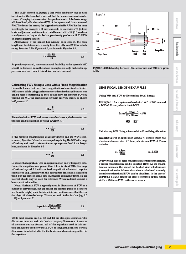
Figure 1.4
Figure 1.4: Relationship between FOV, sensor size, and WD for a given
AFOV.
m = 6.4 mm m = 0.256X
25 mm
/imaging