www.edmundoptics.eu/imaging 21
introduction fundamentals real world telecentricity lens mechanics lens selection guide
performance lens specifications
In many applications, roll-off is not an issue, but it can be a problem
when the chief ray angle becomes steep. This is especially valid for
applications using large or line-scan sensors and applications with
wide AFOVs (short focal length). Table 3.1 shows how roll-off increases
with chief ray angle. Note for an angle of 15°, there is a decrease
in RI of about 13% from the center to the corner, but by doubling the
angle, the roll-off increases to nearly a 44% reduction of RI.
Roll-off must be considered in applications with short WDs and large
FOVs. These types of lenses generally have large chief ray angles in
image-space, regardless of sensor size.
One way to correct for roll-off is by designing the lens to be image
space telecentric. By doing this, the diff erence in the angle of the
chief rays will be 0°, which produces even illumination. Another way
to off set roll-off is to create unbalanced illumination on the object
under inspection. By mounting additional lights closer to the edges of
the object under inspection or by adding an apodizing neutral density
(ND) fi lter onto the lens, roll-off can be reduced.
Roll-Off and Micro Lenses
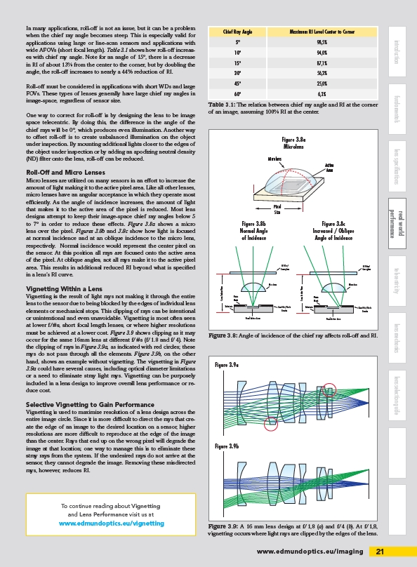
Micro lenses are utilized on many sensors in an eff ort to increase the
amount of light making it to the active pixel area. Like all other lenses,
micro lenses have an angular acceptance in which they operate most
effi ciently. As the angle of incidence increases, the amount of light
that makes it to the active area of the pixel is reduced. Most lens
designs attempt to keep their image-space chief ray angles below 5
to 7° in order to reduce these eff ects. Figure 3.8a shows a micro
lens over the pixel. Figures 3.8b and 3.8c show how light is focused
at normal incidence and at an oblique incidence to the micro lens,
respectively. Normal incidence would represent the center pixel on
the sensor. At this position all rays are focused onto the active area
of the pixel. At oblique angles, not all rays make it to the active pixel
area. This results in additional reduced RI beyond what is specifi ed
in a lens’s RI curve.
Vignetting Within a Lens
Vignetting is the result of light rays not making it through the entire
lens to the sensor due to being blocked by the edges of individual lens
elements or mechanical stops. This clipping of rays can be intentional
or unintentional and even unavoidable. Vignetting is most often seen
at lower f/#s, short focal length lenses, or where higher resolutions
must be achieved at a lower cost. Figure 3.9 shows clipping as it may
occur for the same 16mm lens at diff erent f/#s (f/1.8 and f/4). Note
the clipping of rays in Figure 3.9a, as indicated with red circles; these
rays do not pass through all the elements. Figure 3.9b, on the other
hand, shows an example without vignetting. The vignetting in Figure
3.9a could have several causes, including optical diameter limitations
or a need to eliminate stray light rays. Vignetting can be purposely
included in a lens design to improve overall lens performance or reduce
cost.
Selective Vignetting to Gain Performance
Vignetting is used to maximize resolution of a lens design across the
entire image circle. Since it is more diffi cult to direct the rays that create
the edge of an image to the desired location on a sensor, higher
resolutions are more diffi cult to reproduce at the edge of the image
than the center. Rays that end up on the wrong pixel will degrade the
image at that location; one way to manage this is to eliminate these
stray rays from the system. If the undesired rays do not arrive at the
sensor, they cannot degrade the image. Removing these misdirected
rays, however, reduces RI.
Chief Ray Angle Maximum RI Level Center to Corner
5° 98,5%
10° 94,0%
15° 87,1%
30° 56,3%
45° 25,0%
60° 6,3%
Table 3.1: The relation between chief ray angle and RI at the corner
of an image, assuming 100% RI at the center.
Figure 3.9a
Figure 3.9b
To continue reading about Vignetting
and Lens Performance visit us at
www.edmundoptics.eu/vignetting Figure 3.9: A 16 mm lens design at f/1,8 (a) and f/4 (b). At f/1,8,
vignetting occurs where light rays are clipped by the edges of the lens.
Pixel
Size
IR Filter/
Coverglass
Pixel Active Area
Micro lens
Photo
Mask
Read Out/Clock
Circuits
Substrate
Microlens
Active
Area
Cross Section View
Pixel
Size
Pixel Active Area
Photo
Mask
Substrate
Microlens
Active
Area
Cross Section View
IR Filter/
Coverglass
Micro lens
Photo
Mask
Read Out/Clock
Circuits
Substrate
Cross Section View
Increased / Oblique Angle of Incidence
Pixel Active Area
Figure 3.8b
Normal Angle
of Incidence
Figure 3.8a
Microlens
Figure 3.8c
Increased / Oblique
Angle of Incidence
Figure 3.8: Angle of incidence of the chief ray aff ects roll-off and RI.
/imaging
/vignetting