resources are not available to take full advantage of high-performance
cameras and software. In particular, the ethernet network speed interface
43.3
www.edmundoptics.eu/imaging 153
resource guide fixed focal length telecentric liquid lens / specialty filters/accessories
cameras illumination targets
microscopy /
objectives
Laptops and Cameras
Although many digital camera interfaces are accessible to laptop
computers, it is highly recommended to avoid standard laptops for
high-performance and/or high-speed imaging applications. Often, the
data buses on the laptop will not support full transfer speeds and the
Section 10.2: Powering the Camera
Section 10.3: Camera Software
Section 10.4: Sensors
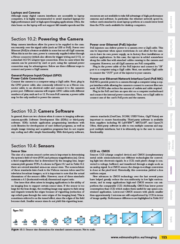
Figure 10.1
4.8 5.8 6.4 7.2
3.6 6.0 4.3 7.2 4.8 8.0 5.4 9.0
Figure 10.1: Sensor size dimensions for standard camera sensors. Not to scale.
cards standard in most laptops perform at a much lower level
than the PCIe cards available for desktop computers.
Many camera interfaces allow for power to be supplied to the camera
remotely over the signal cable (such as USB or PoE). Power over
Ethernet (PoE) is a feature available in some but not all GigE cameras.
When this is not the case, power is commonly supplied either through
a Hirose connector (which also allows for trigger wiring and I/O), or
a standard AC/DC adapter type connection. Even in cases where the
camera can be powered by card or port, using the optional power
connection may be advantageous. Below are three different ways to
connect and power a GigE camera:
General-Purpose Input/Output (GPIO)
Power Cable Connection
Connect the camera to a computer using a GigE cable. Next, plug in
the GPIO power cable, also commonly referred to as a Hirose connector
cable, to an electrical outlet and connect it to the camera’s
power port. Different cameras will require GPIO cables with different
numbers of pins, such as 6 or 12. For non-PoE cameras, a power cable
may be the only method to power the camera.
Power over Ethernet (PoE) Injector
PoE injectors can deliver power to a camera over a GigE cable. This
can be important when space restrictions do not allow for the camera
to have its own power supply, as in factory floor installations or
outdoor applications. In this case, the injector is added somewhere
along the cable line with standard cables running to the camera and
computer. However, not all GigE cameras are PoE compatible.
Plug in the power cable of the PoE injector and connect its “IN”
port to a computer using a GigE cable. Next, use another GigE cable
to connect the “OUT” port of the injector to your camera.
Power over Ethernet Network Interface Card (PoE NIC)
PoE NICs provide power to a camera through a computer using a copper
interface while allowing the camera to connect to a secure fiber network.
PoE NICs also reduce the amount of outlets and cable required.
Plug in the PoE card into an open slot on a computer motherboard
and connect the internal power connection. Then, use a GigE cable to
connect one of the card’s PoE ports and the camera.
Sensor Size
The size of a camera sensor’s active area is important in determining
the system’s field of view (FOV) and primary magnification (m). Given
a fixed magnification that is determined by the imaging lens, larger
sensors yield greater FOVs. As shown in Figure 10.1 and in Table 10.2,
there are several standard area-scan sensor sizes. The nomenclature
of these standards dates back to the Vidicon vacuum tubes used for
television broadcast imagers, so it is important to note that the actual
dimensions of the sensors differ. However, most of these standards
maintain a 4:3 (horizontal:vertical) dimensional aspect ratio.
One issue that often arises in imaging applications is the ability of
an imaging lens to support certain sensor sizes. If the sensor is too
large for the lens design, the resulting image may appear to fade away
and degrade towards the edges because of vignetting (extinction of
rays which pass through the outer edges of the imaging lens). This is
sometimes referred to as the tunnel effect, since the edges of the field
become dark. Smaller sensor sizes do not yield this vignetting issue.
CCD vs. CMOS
Sensors CCD (charge coupled device) and CMOS (complementary
metal oxide semiconductor) use different technologies for converting
light into electronic signals. In a CCD, each pixel’s charge is converted
to voltage, buffered, and transferred through a single node as
an analog signal. In a CMOS sensor, the charge-to-voltage conversion
is done at the pixel level. Historically, this conversion yielded a less
uniform output.
New advances in CMOS technology over the last several years
have helped greatly reduce the non-uniformity in low light environments,
and in many applications high-end CMOS sensors can outperform
the comparable CCD. Additionally, CMOS has lower power
consumption than CCD, which makes them useful for any space-constrained
application. Lower-end CMOS sensors with pixels smaller
than approximately 3 microns are still outperformed by CCD in terms
of image quality. Performance differences are highlighted in Table 10.3
In general, there are two choices when it comes to imaging software:
camera-specific Software Development Kits (SDKs) or third-party
software. SDKs include application programming interfaces with
code libraries for development of user defined programs, as well as
simple image viewing and acquisition programs that do not require
any coding and offer simple functionality. With third-party software,
camera standards (GenICam, DCAM, USB3 Vision, GigE Vision) are
important to ensure functionality. Third-party software is available
from suppliers including NI LabVIEW™, MATLAB®, and OpenCV.
Often, third-party software is able to run multiple cameras and support
multiple interfaces, but it is ultimately up to the user to ensure
functionality.
½ Inch
8.8
6.6 11.0
12.8
9.6 16
1 Inch
17.3
13 21.6
⁄ Inch
22.4
16.8 27.9
APS-C
29.2
20.2 35.5
APS-H
14.08
10.56 17.6
1.1 Inch
24
36
35mm
Inch ½.5 Inch ⁄.8 Inch Inch
/imaging