moving objects are distorted by a rolling shutter; this eff ect can be
minimized with a triggered strobe placed at the point in time where
the integration period of the lines overlaps. Note that this is not an
issue at low speeds. Implementing global shutter for CMOS requires
more complicated sensor architecture than the standard rolling shutter
model, and thus they are not available on all CMOS sensors. A
comparison of global and rolling shutters is shown in Figure 10.3.
Section 10.6:
Area Scan vs. Line Scan Cameras
In contrast to global and rolling shutters, an asynchronous shutter
refers to the triggered exposure of the pixels. That is, the camera is
ready to acquire an image, but it does not enable the pixels until after
receiving an external triggering signal. This is opposed to a normal
constant frame rate, which can be thought of as internal triggering
of the shutter.
Figure 10.4b
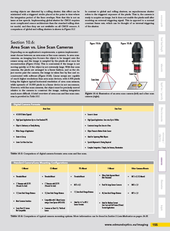
Depending on an application’s requirements, a system implementer
must choose between an area scan or line scan camera. In area scan
cameras, an imaging lens focuses the object to be imaged onto the
sensor array, and the image is sampled by the pixels all at once for
reconstruction (Figure 10.4a). This is convenient if the image is not
moving quickly or if the object is not extremely large. With line scan
cameras, the pixels are arranged in a linear fashion, and as the object
moves past the camera, the image is taken line by line and reconstructed
with software (Figure 10.4b). Linear arrays are capable
of much higher resolutions than area scan devices, with 4.000 pixels
being the highest typical horizontal resolution of area scan sensors,
while upwards of 16.000 pixels in a linear device is not uncommon.
However, with line scan cameras, the object must be precisely moved
relative to the camera to construct the image, making integration
much more diffi cult. A brief overview of area scan and line scan cameras
is provided in Table 10.5.
C-Mount CS-Mount TFL-Mount F-Mount Other Common Mounts
• Threaded Mount • Threaded Mount • Threaded Mount • Nikon-Style Bayonet Mount
(Not Threaded) • M12 x 0,5 (S-Mount)
• 1" Diameter with 32 TPI
(Threads Per Inch) • M35 x 0,5 • Used On Large Sensor Cameras • M42 x 1,0
• 17,5mm Back Flange Distance • 12,5mm Back Flange Distance • 17,5mm Back Flange Distance • 46,5mm Back Flange Distance • M72 x 1,0
• Ideal for Medium Format
Line Scan and Full Frame (35mm)
• Some Short FL Lenses Format Applications
Not Compatible
www.edmundoptics.eu/imaging 155
resource guide fixed focal length telecentric liquid lens / specialty filters/accessories
cameras illumination targets
microscopy /
objectives
Figure 10.4a
Scan Area
Scan Line
Figure 10.4: Illustration of an area scan camera (left) and a line scan
camera (right).
Digital Camera Formats
Area Scan Line Scan
• 4:3 (H:V) Ratio (Typical) • Sensor is Linear
• High Speed Applications Up to a Few Hundred FPS • High Speed Applications- Line rates Up to 100khz
• Object is Stationary or Slowly Moving • Constructs Image One Line at a Time
• Wider Range of Applications • Object Passes in Motion Under Sensor
• Easier to Set-up • Ideal for Capturing Wide Objects
• Lower Cost than Line Scan • Special Alignment & Timing Required
• Complex Integration / Simple, but Intense, Illumination
Table 10.5: Comparison of digital camera formats: area scan and line scan.
Standard Camera/Lens Mounting Confi gurations
• 1" Diameter with 32 TPI
(Threads Per Inch)
• Most Common Interface • Compatible with C-Mount Lenses
using a 5mm Spacer (#03-618) • Ideal for /" to APS-C
Sensor Formats
• Common on Short FL / Varifocal
Lenses
Table 10.6: Comparison of typical camera mounting options. More information can be found in Section 5: Lens Mechanics on pages 34-36.
/imaging