lens
lens
5
45
5
4010
15
10
35
20
15
30
20
2525
25
3020
35
30
15 15
40
40
50mm DG Series Lens
www.edmundoptics.eu/imaging 189
resource guide fixed focal length telecentric liquid lens / specialty filters/accessories
cameras illumination targets
microscopy /
objectives
Section 12.7: Depth of Field (DOF) Targets
DOF targets enable the visualization and quantifi cation of how well
focus is maintained as details move away from the plane the lens is focused
on. DOF targets consist of lines of known frequencies (resolutions)
that are tipped at a known angle and are used to determine how
well focus is maintained. As the lines proceed closer to and farther
away from the lens, the blurrier they become, until they are no longer
able to be distinguished from one another. Contrast measurement can
be made at diff erent distances to determine when the desired level of
resolution is lost; this determines the DOF limit for a lens at a setting.
Figures 12.11 and 12.12 demonstrate how to use a DOF target.
Iris Setting
f/4
Iris Setting
f/8
Iris Setting
f/11
Distortion targets are used to calibrate systems to correctly measure
the optical misplacement of imaging information. These targets consist
of dot, grid, or square patterns; are compatible with the calibration
routines of most imaging software; and can either remap or adjust
measurements across the FOV (Figure 12.14). Figure 12.15 shows
the types of distortion that can be adjusted.
Once the pattern is imaged, the known size and spacing of the pattern
allow adjustments to be made (Figure 12.15).
Section 12.8: Distortion Targets
Figure 12.11: A DOF target
should be at 45° from the lens.
Figure 12.12: Sample confi gurations
using a DOF target.
35
45
40
35
30
25
20
5
10
15
20
25
30
35
45
40
35
30
25
20
4010
45
5
455
45
10
5
15
10
Lens Mounted
at 45º Angle
Lens Mounted
Vertically
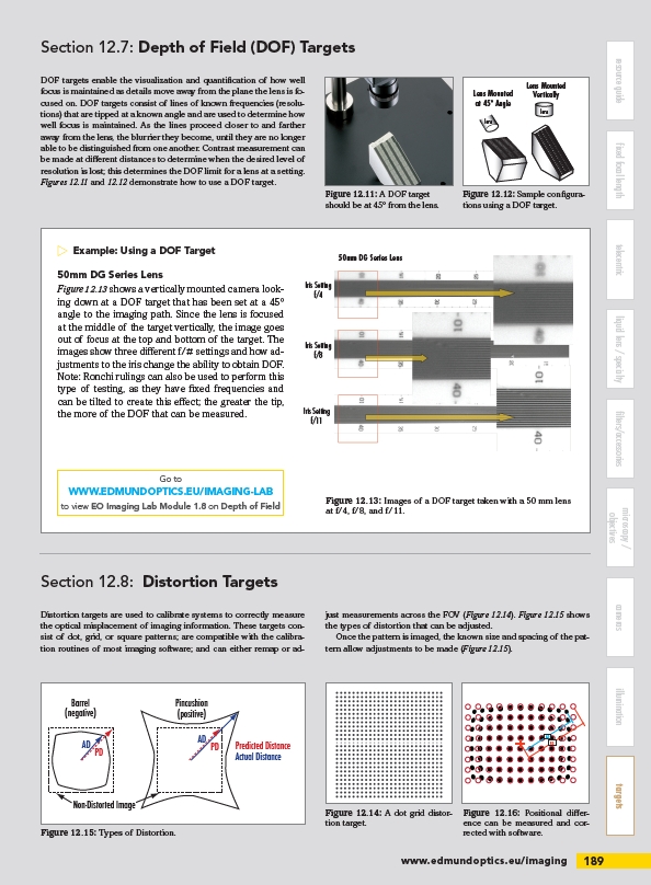
E xample: Using a DOF Target
50mm DG Series Lens
Figure 12.13 shows a vertically mounted camera looking
down at a DOF target that has been set at a 45°
angle to the imaging path. Since the lens is focused
at the middle of the target vertically, the image goes
out of focus at the top and bottom of the target. The
images show three diff erent f/# settings and how adjustments
to the iris change the ability to obtain DOF.
Note: Ronchi rulings can also be used to perform this
type of testing, as they have fi xed frequencies and
can be tilted to create this eff ect; the greater the tip,
the more of the DOF that can be measured.
Figure 12.13: Images of a DOF target taken with a 50 mm lens
at f/4, f/8, and f/11.
Go to
WWW.EDMUNDOPTICS.EU/IMAGING-LAB
to view EO Imaging Lab Module 1.8 on Depth of Field
PD
AD
AD PD
Figure 12.15: Types of Distortion.
Figure 12.16: Positional diff erence
can be measured and corrected
with software.
Figure 12.14: A dot grid distortion
target.
PD
AD
Predicted Distance
Actual Distance
Barrel
(negative)
Pincushion
(positive)
Non-Distorted Image
/imaging
/IMAGING-LAB