Section 1: Lens and Imaging Fundamentals
Working
Distance Range
Thumbscrews
Focus 50mm
1.85 2 2.8 8 11
f/# Tick
Marks
6mm/F1.85 #33-301
EDMUND OPTICS®
Focus
Adjustment
Ring
Overall Length
Adjustment
Ring
H
m =
FOV
Lens
Manufacturer Focal
Length
Minimum f/#
Part
Number
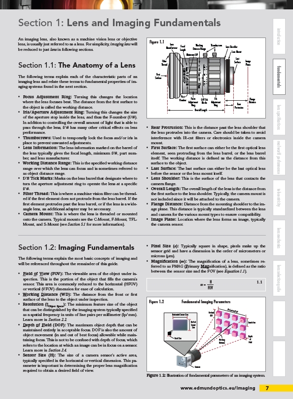
Figure 1.1
First
Surface
Iris
Lens Shoulder
Filter
Thread
Figure 1.2 Fundamental Imaging Parameters
1.1
Last
Surface Image
Plane
Flange
Distance
Lens Mount
Rear
Protrusion
www.edmundoptics.eu/imaging 7
introduction fundamentals lens specifications real world performance telecentricity lens mechanics lens selection guide
An imaging lens, also known as a machine vision lens or objective
lens, is usually just referred to as a lens. For simplicity, imaging lens will
be reduced to just lens in following sections.
Section 1.1: The Anatomy of a Lens
The following terms explain each of the characteristic parts of an
imaging lens and relate these terms to fundamental properties of imaging
systems found in the next section.
• Focus Adjustment Ring: Turning this changes the location
where the lens focuses best. The distance from the fi rst surface to
the object is called the working distance.
• Iris/Aperture Adjustment Ring: Turning this changes the size
of the aperture stop inside the lens, and thus the F-number (f/#).
In addition to controlling the overall amount of light that is able to
pass through the lens, f/# has many other critical eff ects on lens
performance.
• Thumbscrews: Used to temporarily lock the focus and/or iris in
place to prevent unwanted adjustments.
• Lens Information: The lens information marked on the barrel of
the lens typically gives the focal length, minimum f/#, part number,
and lens manufacturer.
• Working Distance Range: This is the specifi ed working distance
range over which the lens can focus and is sometimes referred to
as object distance range.
• f/# Tick Marks: Marks on the lens barrel that designate where to
turn the aperture adjustment ring to operate the lens at a specifi c
f/#.
• Filter Thread: This is where a machine vision fi lter can be threaded
if the fi rst element does not protrude from the lens barrel. If the
fi rst element protrudes past the lens barrel, or if the lens is a wideangle
lens, an additional adapter may be necessary.
• Camera Mount: This is where the lens is threaded or mounted
onto the camera. Typical mounts are the C-Mount, F-Mount, TFLMount,
and S-Mount (see Section 5.1 for more information).
• Rear Protrusion: This is the distance past the lens shoulder that
the lens protrudes into the camera. Care should be taken to avoid
interference with IR-cut fi lters or electronics inside the camera
mount.
• First Surface: The fi rst surface can either be the fi rst optical lens
element, seen protruding from the lens barrel, or the lens barrel
itself. The working distance is defi ned as the distance from this
surface to the object.
• Last Surface: The last surface can either be the last optical lens
before the sensor or the lens mount itself.
• Lens Shoulder: This is the surface of the lens that contacts the
camera fl ange.
• Overall Length: The overall length of the lens is the distance from
the fi rst surface to the lens shoulder. Typically, the camera mount is
not included since it will be attached to the camera.
• Flange Distance: Distance from the mounting shoulder to the image
plane. This distance is typically standardized between the lens
and camera for the various mount types to ensure compatibility.
• Image Plane: Location where the lens forms an image, typically
the camera sensor.
Section 1.2: Imaging Fundamentals
The following terms explain the most basic concepts of imaging and
will be referenced throughout the remainder of this guide.
• Field of View (FOV): The viewable area of the object under inspection.
This is the portion of the object that fi lls the camera’s
sensor. This area is commonly reduced to the horizontal (HFOV)
or vertical (VFOV) dimension for ease of calculation.
• Working Distance (WD): The distance from the front or fi rst
surface of the lens to the object under inspection.
• Resolution (ξObject Space): The minimum feature size of the object
that can be distinguished by the imaging system typically specifi ed
as a spatial frequency in units of line pairs per millimeter (lp/mm).
Learn more in Section 2.2.
• Depth of Field (DOF): The maximum object depth that can be
maintained entirely in acceptable focus. DOF is also the amount of
object movement (in and out of best focus) allowable while maintaining
focus. This is not to be confused with depth of focus, which
refers to the location at which an image can be in focus on a sensor.
Learn more in Section 3.4.
• Sensor Size (H): The size of a camera sensor’s active area,
typically specifi ed in the horizontal or vertical dimension. This parameter
is important in determining the proper lens magnifi cation
required to obtain a desired fi eld of view.
• Pixel Size (s): Typically square in shape, pixels make up the
sensor grid and have a dimension in the order of micrometers or
microns (μm).
• Magnifi cation (m): The magnifi cation of a lens, sometimes referred
to as PMAG (Primary Magnifi cation), is defi ned as the ratio
between the sensor size and the FOV (see Equation 1.1).
Horizontal Sensor Size
Horizontal FOV
Vertical
Sensor
Size
Resolution
Vertical
FOV
Depth
of
Field
Working
Distance
Camera
Pixel Size
Figure 1.2: Illustration of fundamental parameters of an imaging system.
/imaging
/