Figure 3.30 Field Curvature
Actual
Reference
Figure 3.30: A fi eld curvature example showing the non-planer surface
Figure 3.31 Chromatic Focal Shift
Red
Blue
Image Plane
Plano-Convex Lens
Red
Red & Blue
All Wavelengths
White Light
Image Plane
Red
Blue
Achromatic Lens
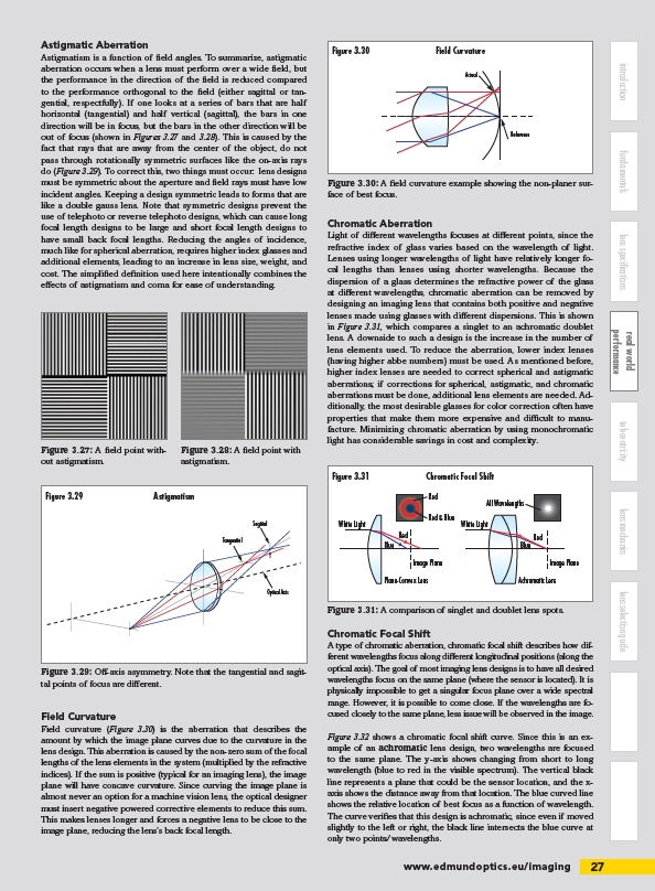
Figure 3.31: A comparison of singlet and doublet lens spots.
www.edmundoptics.eu/imaging 27
introduction fundamentals real world telecentricity lens mechanics lens selection guide
performance lens specifications
Astigmatic Aberration
Astigmatism is a function of fi eld angles. To summarize, astigmatic
aberration occurs when a lens must perform over a wide fi eld, but
the performance in the direction of the fi eld is reduced compared
to the performance orthogonal to the fi eld (either sagittal or tangential,
respectfully). If one looks at a series of bars that are half
horizontal (tangential) and half vertical (sagittal), the bars in one
direction will be in focus, but the bars in the other direction will be
out of focus (shown in Figures 3.27 and 3.28). This is caused by the
fact that rays that are away from the center of the object, do not
pass through rotationally symmetric surfaces like the on-axis rays
do (Figure 3.29). To correct this, two things must occur: lens designs
must be symmetric about the aperture and fi eld rays must have low
incident angles. Keeping a design symmetric leads to forms that are
like a double gauss lens. Note that symmetric designs prevent the
use of telephoto or reverse telephoto designs, which can cause long
focal length designs to be large and short focal length designs to
have small back focal lengths. Reducing the angles of incidence,
much like for spherical aberration, requires higher index glasses and
additional elements, leading to an increase in lens size, weight, and
cost. The simplifi ed defi nition used here intentionally combines the
eff ects of astigmatism and coma for ease of understanding.
Figure 3.27: A fi eld point without
astigmatism.
Figure 3.28: A fi eld point with
astigmatism.
Tangential
Sagittal
Optical Axis
Figure 3.29 Astigmatism
Figure 3.29: Off -axis asymmetry. Note that the tangential and sagittal
points of focus are diff erent.
Field Curvature
Field curvature (Figure 3.30) is the aberration that describes the
amount by which the image plane curves due to the curvature in the
lens design. This aberration is caused by the non-zero sum of the focal
lengths of the lens elements in the system (multiplied by the refractive
indices). If the sum is positive (typical for an imaging lens), the image
plane will have concave curvature. Since curving the image plane is
almost never an option for a machine vision lens, the optical designer
must insert negative powered corrective elements to reduce this sum.
This makes lenses longer and forces a negative lens to be close to the
image plane, reducing the lens’s back focal length.
of best focus.
Chromatic Aberration
Light of diff erent wavelengths focuses at diff erent points, since the
refractive index of glass varies based on the wavelength of light.
Lenses using longer wavelengths of light have relatively longer focal
lengths than lenses using shorter wavelengths. Because the
dispersion of a glass determines the refractive power of the glass
at diff erent wavelengths, chromatic aberration can be removed by
designing an imaging lens that contains both positive and negative
lenses made using glasses with diff erent dispersions. This is shown
in Figure 3.31, which compares a singlet to an achromatic doublet
lens. A downside to such a design is the increase in the number of
lens elements used. To reduce the aberration, lower index lenses
(having higher abbe numbers) must be used. As mentioned before,
higher index lenses are needed to correct spherical and astigmatic
aberrations; if corrections for spherical, astigmatic, and chromatic
aberrations must be done, additional lens elements are needed. Additionally,
the most desirable glasses for color correction often have
properties that make them more expensive and diffi cult to manufacture.
Minimizing chromatic aberration by using monochromatic
light has considerable savings in cost and complexity.
White Light
Chromatic Focal Shift
A type of chromatic aberration, chromatic focal shift describes how different
wavelengths focus along diff erent longitudinal positions (along the
optical axis). The goal of most imaging lens designs is to have all desired
wavelengths focus on the same plane (where the sensor is located). It is
physically impossible to get a singular focus plane over a wide spectral
range. However, it is possible to come close. If the wavelengths are focused
closely to the same plane, less issue will be observed in the image.
Figure 3.32 shows a chromatic focal shift curve. Since this is an example
of an achromatic lens design, two wavelengths are focused
to the same plane. The y-axis shows changing from short to long
wavelength (blue to red in the visible spectrum). The vertical black
line represents a plane that could be the sensor location, and the xaxis
shows the distance away from that location. The blue curved line
shows the relative location of best focus as a function of wavelength.
The curve verifi es that this design is achromatic, since even if moved
slightly to the left or right, the black line intersects the blue curve at
only two points/wavelengths.
/imaging