Figure 11.6a Figure 11.6b
A
B
C
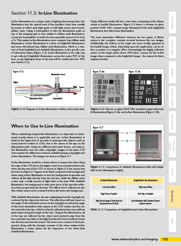
When to Use In-Line Illumination Figure 11.7
Figure 11.7: Comparison of darkfi eld illumination (left) with brightfi
eld in-line illumination (right).
Darkfi eld Illumination Brightfi eld In-line Illumination
Low Contrast Wires High Contrast Wires
Bright Chip on Faceplate Dark Chip on Faceplate
High Contrast Image in Some Areas but
Inconsistent Across the Field
Even Illumination with Consistent Contrast
between Features
www.edmundoptics.eu/imaging 173
resource guide fixed focal length filters/accessories cameras targets
telecentric liquid lens / specialty illumination
microscopy /
objectives
Section 11.3: In-Line Illumination
In-line illumination is a unique style of lighting that incorporates the
illumination into the optical train of the machine vision lens, usually
by means of a fi ber optic light guide or LED light source and a beamsplitter
optic. Using a beamsplitter to fold the illumination path on
top of the imaging path is very similar to diff use axial illumination,
except the beamsplitter is inside the lens assembly instead of in front
of it. This makes in-line illumination more compact than diff use axial
illumination. In-line illumination is a form of brightfi eld illumination
and more directional than diff use axial illumination, which is a mixture
of both brightfi eld and darkfi eld illumination. In the specifi c case
of telecentric lenses (Figure 11.5), in-line illumination is the only way
to get refl ected brightfi eld illumination across the entire FOV of the
lens, as any lighting in front of the lens will be outside the lens’ FOV
(see Section 11.1).
Vastly diff erent results will also come from comparing in-line illumination
to backlit illumination. Figure 11.6 shows a chrome on glass,
positive USAF 1951 contrast target illuminated both with brightfi eld
illumination and with in-line illumination.
The most immediate diff erence between the two types of illumination
is the complete contrast reversal between the two images.
Additionally, the defects in the target are more readily apparent in
the backlit image, which, depending upon the application, can be either
a positive or a negative eff ect. Interestingly, the highly refl ective
nature of the target yields about 10% better contrast for the in-line
image when compared to the brightfi eld image – the reason for this is
explained below.
Figure 11.6: Chrome on glass USAF 1951 resolution target with backlit
illumination (Figure 11.6a), and in-line illumination (Figure 11.6b).
Illumination Source
Sensor
Beamsplitter
Figure 11.5
Object
Illumination Path
Figure 11.5: Diagram of in-line illumination within a telecentric lens.
Table 11.1: Comparison of brightfi eld and in-line illumination.
When considering using in-line illumination, it is important to understand
exactly where it is applicable and not. In-line illumination is
ideal for the inspection of specular or semi-specular objects, such as
semiconductor wafers or CCDs, due to the nature of the rays on the
illumination path. Using two diff erent telecentric lenses, one with inline
illumination and one with a ring light, images of the same CCD
demonstrate the diff erences between darkfi eld (using a ring light) and
in-line illumination. The images are shown in Figure 11.7.
In-line illumination would be a better choice to inspect the wires along
the edge of the CCD due to the higher, more even contrast between the
wires and the rest of the CCD. As shown in Figure 11.8, the reason that
the wires in Figure 11.7 appear more black compared to the background
when using in-line illumination is that the background is specular and
refl ects all the light directly back into the lens, while the diff use wires
scatter only a small amount of light back to the lens. With darkfi eld
illumination, the background is dark since most of the specular refl ection
does not get back into the lens. The diff use wires’ refl ection is also
dim, which causes a low contrast between the wires and background.
With darkfi eld illumination, the rays originating from the ring light are
scattered by the object into the lens. The refl ections will vary based on
the angle of the individual sources in the ring light as well as the angle
of the wires themselves with respect to the CCD surface and the solder
material at the tips, which is why the refl ections have non-uniform
pixel values along the length of the wire. Using in-line illumination, all
of the rays are refl ected by the object and scattered away from the
lens such that very little of the light that hits the wires is refl ected back
into the lens and onto the sensor. The more even contrast of the background,
along with the stronger contrast of the wires, makes in-line
illumination a better choice for the inspection of the wires than
darkfi eld illumination.
/imaging