illumination cameras microscopy / objectives filters / accessories liquid lens / specialty telecentric fixed focal length resource guide
Sharp Transition
Shallow Transition
Figure 4.3b
Section 4.2: Distortion and the Telecentricity Specifi cation
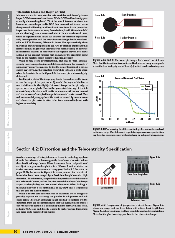
Another advantage of using telecentric lenses in metrology applications
is that telecentric lenses typically have lower distortion values
than fi xed focal length lenses. Distortion causes the actual position of
an object to appear as though it is in a diff erent location, which can
further decrease measurement accuracy (see Section 3.3: Distortion on
pages 22-23). For example, Figure 4.5a shows jumper pins on a circuit
board that have been imaged by a fi xed focal length lens with high
distortion. The distortion, coupled with the parallax error inherent to
non-telecentric lenses, makes the pins toward the edge of the image
appear as though they are bent toward the center. When looking at
the same pins with a telecentric lens, as in Figure 4.5b, it is apparent
that the pins are indeed straight.
While it is true that distortion can be calibrated out of images to
partially improve the accuracy, the parallax is still present and will
cause error. The other advantage in not needing to calibrate out the
distortion from the telecentric lens is that the measurement process
can run faster as there is less computing that the software needs to do,
reducing CPU load and directly leading to higher system throughput
and more parts measured per minute.
30 +44 (0) 1904 788600 | Edmund Optics® targets Focus and Defocused Pixel Values
Figure 4.3a
Figure 4.4
395 400 405 410 415 420 425 430
Pixel Position
Grey Scale
300
250
200
150
100
50
0
Focused
Defocused
Figure 4.4: Plot showing the diff erence in slope between a focused and
defocused edge. The defocused edge takes up many more pixels; fi nding
the edge becomes easier without relying on sub-pixel interpolation.
Telecentric Lenses and Depth of Field
It is a common misconception that telecentric lenses inherently have a
larger DOF than conventional lenses. While DOF is still ultimately governed
by the wavelength and f/# of the lens, it is true that telecentric
lenses can have a larger usable DOF than conventional lenses due to
the symmetrical blurring on either side of best focus. As the part under
inspection shifts toward or away from the lens, it will follow the AFOV
(or the chief ray) that is associated with it. In a non-telecentric lens,
when an object is moved in and out of focus, the part blurs asymmetrically
due to parallax and the magnifi cation change that is associated
with its AFOV. However, Telecentric lenses blur symmetrically since
there is no angular component to the FOV. In practice, this means that
features such as edges retain their center of mass location; an accurate
measurement can still be made when the object is beyond best focus
as long as the contrast remains high enough for the algorithm being
used by the machine vision system to function properly.
While it may seem counterintuitive, blur can be used advantageously
in certain applications with telecentric lenses. For example, if
a machine vision system needs to fi nd the center location of a pin, as
shown in Figure 4.3a, the transition from white to black is quite sharp
when the lens is in focus. In Figure 4.3b, the same pin is shown slightly
defocused.
Looking at a plot of the image grey levels from a line profi le taken
across the edge of the part, as in Figure 4.4, the slope of the line is
much shallower for the slightly defocused image, as the pin edge is
spread over more pixels. Due to the symmetric blurring of the telecentric
lens, this blur is still usable as the centroid has not moved
and the amount of sub-pixel interpolation needed is decreased. This
reduces sensitivity to grey level fl uctuations caused by sensor noise
and allows the pin center location to be found more reliably and with
higher repeatability.
Figure 4.3a and b: The same pin imaged both in and out of focus.
Note that the transition from white to black covers many more pixels
when the lens is slightly out of focus (b), which can be advantageous.
Fixed Focal Length Lens
F-STOP
FOCUS
45°
Arrangement
Telecentric Lens
Figure 4.5a
Figure 4.5b
Figure 4.5: Comparison of jumpers on a circuit board. Figure 4.5a
shows an image that has been taken with a fi xed focal length lens.
Figure 4.5b shows an image that has been taken with a telecentric lens.
Note that the pins do not appear bent in the telecentric image.