Ø0.4mm, Dig #40
www.edmundoptics.eu/LO 29
Section 9:
Surface Quality
The surface quality of an optical component is an evaluation of the surface
imperfections, such as scratches and pits, or digs, which may be
caused during the manufacturing or handling process. Surface quality is
more important for laser applications than imaging applications because
surface imperfections can be the initiating sites for laser induced damage.
Optics used with UV wavelengths require tighter surface quality
tolerances than optics used with visible or IR systems because shorter
wavelengths experience higher amounts of scatter. There are several
standards for specifying surface quality such as U.S. Military Performance
Specifi cation MIL-PRF-13830B and ISO 10110.
Section 9.1:
U.S. Standard MIL-PRF-13830B
The U.S. Military Performance Specifi cation MIL-PRF-13830B describes
surface quality using a “scratch” number followed by a “dig” number
based on calibrated standards prescribed therein,1 The scratch number
is one of the following arbitrary numbers: 10, 20, 40, 60, or 80, where
brightness of scratches increases from 10 to 80. This number is not an
exact measurement, only an indication of the best match of component
scratch brightness with calibrated standard scratch brightness.
The inspection occurs under specifi ed darkfi eld illumination conditions,
but because it is a subjective visual inspection the results can vary
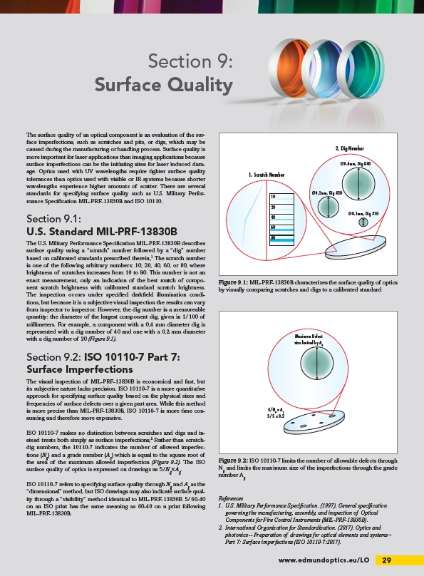
from inspector to inspector. However, the dig number is a measureable
quantity: the diameter of the largest component dig, given in 1/100 of
millimeters. For example, a component with a 0,4 mm diameter dig is
represented with a dig number of 40 and one with a 0,2 mm diameter
with a dig number of 20 (Figure 9.1).
Section 9.2: ISO 10110-7 Part 7:
Surface Imperfections
The visual inspection of MIL-PRF-13830B is economical and fast, but
its subjective nature lacks precision. ISO 10110-7 is a more quantitative
approach for specifying surface quality based on the physical sizes and
frequencies of surface defects over a given part area. While this method
is more precise than MIL-PRF-13830B, ISO 10110-7 is more time consuming
and therefore more expensive.
ISO 10110-7 makes no distinction between scratches and digs and instead
treats both simply as surface imperfections,2 Rather than scratchdig
numbers, the 10110-7 indicates the number of allowed imperfections
(Ng) and a grade number (Ag) which is equal to the square root of
the area of the maximum allowed imperfection (Figure 9.2). The ISO
surface quality of optics is expressed on drawings as 5/Ng×Ag.
ISO 10110-7 refers to specifying surface quality through Ng and Ag as the
“dimensional” method, but ISO drawings may also indicate surface quality
through a “visibility” method identical to MIL-PRF-13830B. 5/60-40
on an ISO print has the same meaning as 60-40 on a print following
MIL-PRF-13830B.
1. Scratch Number
2. Dig Number
10
20
40
60
80
Ø0.1mm, Dig #10
Ø0.2mm, Dig #20
Figure 9.1: MIL-PRF-13830B characterizes the surface quality of optics
by visually comparing scratches and digs to a calibrated standard
Maximum Defect
size limited by Ag
5/Ng x Ag
5/5 x 0.2
Figure 9.2: ISO 10110-7 limits the number of allowable defects through
Ng and limits the maximum size of the imperfections through the grade
number Ag
References
1. U.S. Military Performance Specifi cation. (1997). General specifi cation
governing the manufacturing, assembly, and inspection of Optical
Components for Fire Control Instruments (MIL-PRF-13830B).
2. International Organization for Standardization. (2017). Optics and
photonics -- Preparation of drawings for optical elements and systems –
Part 7: Surface imperfections (ISO 10110-7:2017).
/LO