Gaussian and Flat Top Beam Profiles
Gaussian
1
0.7
0.5
0.4
0.3
0.2
0.1
www.edmundoptics.eu/LO 7
Section 1.2: Beam Parameters
The following parameters characterize the shape and quality of laser
beams.
5: Beam Diameter (Typical Units: mm to cm)
A laser’s beam diameter characterizes the transverse extension of the
beam, or its physical size perpendicular to the direction of propagation.
It is often defined at the 1/e2 width, which is bounded by the points
where the beam’s intensity reaches 1/e2 (≈ 13,5%) of its maximum value.
At the 1/e2 point, the electric field strength drops to 1/e (≈ 37%) of
the maximum value. The larger the beam diameter, the larger the optics
and the overall system need to be to avoid clipping the beam, which
adds cost. However, decreasing beam diameter increases the power/
energy density, which can also be detrimental (see next parameter).
6: Power or Energy Density (Typical Units: W/cm2 to MW/cm2 or
μJ/cm2 to J/cm2)
Beam diameter is related to the power/energy density, or the optical
power/energy per unit area, of a laser beam. The larger the beam diameter,
the smaller the power/energy density of a beam of constant
power or energy. High power/energy densities are often ideal at the
final output of a system (such as in laser cutting or welding), but low
power/energy densities are often beneficial inside a system to prevent
laser-induced damage. This also prevents high power/energy density
regions of the beam from ionizing the air. For these reasons, among
others, beam expanders are often used to increase the diameter, and
thereby decrease the power/energy density inside of a laser system.
However, care must be taken to not expand a beam so much that it
experiences clipping from apertures in the system, leading to wasted
energy and potential damage.
7: Beam Profile
A laser’s beam profile describes the distribution intensity at a cross-section
of the beam. Common beam profiles include Gaussian and flat top
beams, whose beam profiles follow Gaussian and flat top functions, respectively
(Figure 1,4). However, no laser can produce a perfectly Gaussian
or perfectly flat top beam whose beam profile matches its characteristic
function perfectly, as there is always some amount of hotspots or
fluctuations inside a laser. The difference between a laser’s actual beam
profile and that of an ideal beam is often described through metrics including
a laser’s M2 factor. More information about beam profiles and
characterizing beam quality can be found in Section 2: Gaussian Beam
Propagation from pages 8-12 and Section 3: Beam Shape, Beam Quality,
and Strehl Ratio from pages 13-16.
8: Divergence (Typical Units: mrad)
While laser beams are often assumed to be collimated, they always contain
some amount of divergence, which describes how much the beam
spreads out over increasing distance from the laser’s beam waist, because
of diffraction. Divergence becomes an especially significant issue
in applications with a long working distance, such as LIDAR systems
where an object may be hundreds of meters away from the laser system.
Beam divergence is typically defined by the laser’s half angle, and the
divergence (θ) of a Gaussian beam is defined as:
λ is the laser’s wavelength and w0 is the laser’s beam waist. More information
about divergence can be found in in Section 2: Gaussian Beam
Propagation from pages 8-12. Divergence can be decreased by increasing
the beam diameter, as described in Section 5: Laser Beam Expanders
from pages 19-20.
Section 1.3: Final System Parameters
These final parameters describe the performance at the output of laser
systems.
-200 -100 0 100
Flat Top
Relative Intensity
Radial Pos.
(m)
0.9
0.8
0.6
0
Figure 1,4: A comparison of the beam profiles of Gaussian and flat top
beams with the same average power or intensity shows that the Gaussian
beam will have a peak intensity 2X that of the flat top beam
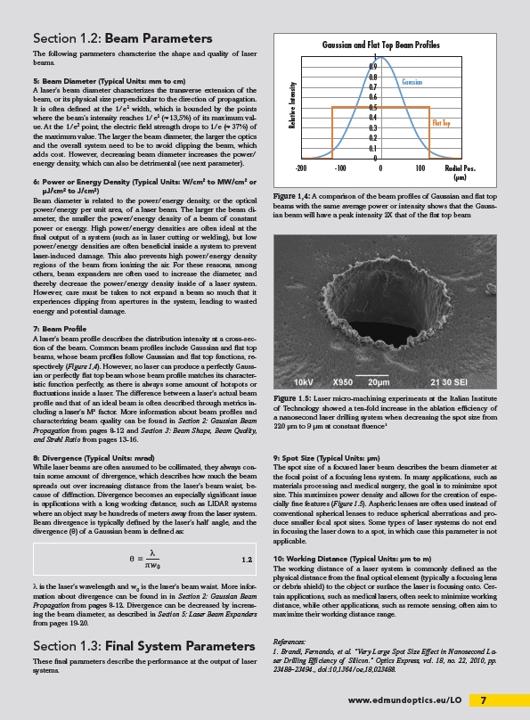
Figure 1.5: Laser micro-machining experiments at the Italian Institute
of Technology showed a ten-fold increase in the ablation efficiency of
a nanosecond laser drilling system when decreasing the spot size from
220 μm to 9 μm at constant fluence1
1.2
9: Spot Size (Typical Units: μm)
The spot size of a focused laser beam describes the beam diameter at
the focal point of a focusing lens system. In many applications, such as
materials processing and medical surgery, the goal is to minimize spot
size. This maximizes power density and allows for the creation of especially
fine features (Figure 1.5). Aspheric lenses are often used instead of
conventional spherical lenses to reduce spherical aberrations and produce
smaller focal spot sizes. Some types of laser systems do not end
in focusing the laser down to a spot, in which case this parameter is not
applicable.
10: Working Distance (Typical Units: μm to m)
The working distance of a laser system is commonly defined as the
physical distance from the final optical element (typically a focusing lens
or debris shield) to the object or surface the laser is focusing onto. Certain
applications, such as medical lasers, often seek to minimize working
distance, while other applications, such as remote sensing, often aim to
maximize their working distance range.
References:
1. Brandi, Fernando, et al. “Very Large Spot Size Effect in Nanosecond Laser
Drilling Efficiency of Silicon.” Optics Express, vol. 18, no. 22, 2010, pp.
23488–23494., doi:10,1364/oe,18,023488.
/LO