Section 11:
Optical Coatings
Optical coatings are used to enhance the transmission, refl ection, or polarization
properties of an optical component. For example, about 4%
of incident light will be refl ected at each surface of an uncoated glass
component. An anti-refl ection coating could be applied to reduce the
refl ection at each surface to less than 0,1% and a highly refl ective dielectric
coating could also be applied to increase refl ectivity to more
than 99,99%. An optical coating is composed of a combination of thin
layers of materials such as oxides, metals, or rare earth materials. The
performance of an optical coating is dependent on the number of layers,
their thickness, and the refractive index diff erence between them.
This section discusses optical coating theory, diff erent types of common
coatings, and coating manufacturing methods.
Section 11.1:
Introduction to Optical Coatings
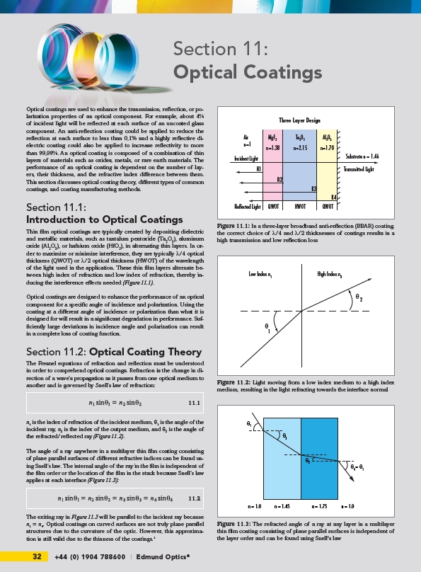
Thin fi lm optical coatings are typically created by depositing dielectric
and metallic materials, such as tantalum pentoxide (Ta2O5), aluminum
oxide (Al2O3), or hafnium oxide (HfO2), in alternating thin layers. In order
to maximize or minimize interference, they are typically λ/4 optical
thickness (QWOT) or λ/2 optical thickness (HWOT) of the wavelength
of the light used in the application. These thin fi lm layers alternate between
high index of refraction and low index of refraction, thereby inducing
the interference eff ects needed (Figure 11.1).
Optical coatings are designed to enhance the performance of an optical
component for a specifi c angle of incidence and polarization. Using the
coating at a diff erent angle of incidence or polarization than what it is
designed for will result in a signifi cant degradation in performance. Suffi
ciently large deviations in incidence angle and polarization can result
in a complete loss of coating function.
Section 11.2: Optical Coating Theory
The Fresnel equations of refraction and refl ection must be understood
in order to comprehend optical coatings. Refraction is the change in direction
of a wave’s propagation as it passes from one optical medium to
another and is governed by Snell’s law of refraction:
n₁ is the index of refraction of the incident medium, θ₁ is the angle of the
incident ray, n₂ is the index of the output medium, and θ₂ is the angle of
the refracted/refl ected ray (Figure 11.2).
The angle of a ray anywhere in a multilayer thin fi lm coating consisting
of plane parallel surfaces of diff erent refractive indices can be found using
Snell’s law. The internal angle of the ray in the fi lm is independent of
the fi lm order or the location of the fi lm in the stack because Snell’s law
applies at each interface (Figure 11.3):
The exiting ray in Figure 11.3 will be parallel to the incident ray because
n₁ = n₄. Optical coatings on curved surfaces are not truly plane parallel
structures due to the curvature of the optic. However, this approximation
is still valid due to the thinness of the coatings.¹
32 +44 (0) 1904 788600 | Edmund Optics®
R1
Three Layer Design
Ta205 Al203
n=1.38 n=2.15 n=1.70
R2
R3
R4
MgF2
Air
n=1
Incident Light
Substrate n = 1.46
Transmitted Light
Reflected Light QWOT HWOT QWOT
Figure 11.1: In a three-layer broadband anti-refl ection (BBAR) coating,
the correct choice of λ/4 and λ/2 thicknesses of coatings results in a
high transmission and low refl ection loss
Low Index n1 High Index n2
2
1
θ
θ
Figure 11.2: Light moving from a low index medium to a high index
medium, resulting in the light refracting towards the interface normal
11.1
11.2
1
2
3
4 = 1
n = 1.0 n = 1.45 n = 1.75 n = 1.0
Figure 11.3: The refracted angle of a ray at any layer in a multilayer
thin fi lm coating consisting of plane parallel surfaces is independent of
the layer order and can be found using Snell's law