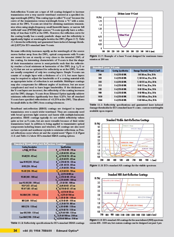
Anti-reflection V-coats are a type of AR coating designed to increase
transmission over a very narrow waveband centered at a specified design
wavelength (DWL). This coating type is called “V-coat” because the
curve of the transmission versus wavelength forms a “V,” with a minimum
at the DWL. V-coats are ideal for obtaining maximum transmission
when using single-frequency, small linewidth lasers, or narrow full
width-half max (FWHM) light sources,3 V-coats typically have a reflectivity
of less than 0,25% at the DWL. However, the reflection curve for
the coating locally has a nearly parabolic shape and the reflectivity is
significantly higher at wavelengths besides the DWL (Figure 11.7). Table
11.1 shows the reflectivity and guaranteed laser-induced damage threshold
(LIDT) for EO’s standard laser V-coats.
Because reflectivity increases rapidly as the wavelength of the source
moves further away from the DWL, optical components with V-coats
are meant for use at exactly or very close to the intended DWL of
the coating. An interesting characteristic of V-coats is that the shape
of their transmission curves is semi-periodic such that the reflectivity
reaches a local minimum at harmonics of the DWL (e.g. λ₀/2 or
λ₀/4) that are not as optimized for reflectivity as at the DWL. V-coats
are usually comprised of only two coating layers. Simple V-coats can
consist of a single layer with a thickness of a λ/4, but more layers
may be required to adjust the bandwidth or if a coating material with
an appropriate index of refraction is not available. Multilayer coatings
may also compensate for different angles of incidence, but are more
complicated and tend to have larger bandwidths. If the thickness of
the V-coat layers are incorrect, the reflectivity of the coating increases
and the DWL changes. V-coats from Edmund Optics typically achieve
minimum reflectivities significantly less than 0,25%, but all standard
V-coats have specified reflectivities of <0,25% at the DWL. This allows
for small shifts in the DWL from coating tolerances.
Broadband anti-reflection (BBAR) coatings are designed to improve
transmission over a much wider waveband. They are commonly used
with broad spectrum light sources and lasers with multiple-harmonic
generation. BBAR coatings typically do not exhibit reflectivity values
quite as low as V-coats, but are more versatile because of their wider
transmission band. In addition to being applied to transmissive optical
components including lenses and windows, AR coatings are also used
on laser crystals and nonlinear crystals to minimize reflections, as Fresnel
reflections occur where air and the crystal meet.³ Figure 11.8, Figure
11.9, and Table 11.2 show EO’s standard BBAR coating options.
Standard Broadband Anti-Reflection Coatings
Coating Description Specifications
l/4 MgF2 @ 550 nm Ravg ≤1,75% @ 400 - 700 nm
UV-AR 250 - 425 nm
Rabs ≤1,0% @ 250 - 425 nm
Ravg ≤0,75% @ 250 - 425 nm
Ravg ≤0,5% @ 370 - 420 nm
Laser UV-VIS 250 - 532 nm Ravg ≤1,25% @ 250 - 532 nm
UV-VIS 250 - 700 nm
Rabs ≤1,0% @ 350 - 450 nm
Ravg ≤1,5% @ 250 - 700 nm
VIS-EXT 350 - 700 nm Ravg <0,5% @ 350 - 700 nm
VIS-NIR 400 - 1000 nm
Rabs ≤0,25% @ 880 nm
Ravg ≤1,25% @ 400 - 870 nm
Ravg ≤1,25% @ 890 - 1000 nm
Laser VIS-NIR 500 - 1090 nm Ravg ≤1% @ 500 - 1090 nm
VIS 0° 425 - 675 nm Ravg ≤0,4% @ 425 - 675 nm
VIS 45° 425 - 675 nm Ravg ≤0,75% @ 425 - 675 nm
YAG-BBAR 500 - 1100 nm
Rabs <0,25% @ 532 nm
Rabs <0,25% @ 1064 nm
Ravg <1,0% @ 500 - 1100 nm
NIR I 600 - 1050 nm Ravg ≤0,5% @ 600 - 1050 nm
NIR II 750 - 1550 nm
Rabs ≤1,5% @ 750 - 800 nm
Rabs ≤1,0% @ 800 - 1550 nm
Ravg ≤0,7% @ 750 - 1550 nm
Laser NIR 1030 - 1550 nm Ravg ≤0,7% @ 1030 - 1550 nm
2 μm BBAR 1900 - 2100 nm
Ravg <0,5% @ 1900 nm - 2100 nm
Ravg <0,25% @ 2000 nm - 2100 nm
34 +44 (0) 1904 788600 | Edmund Optics®
R (%)
1.75
1.5
1.25
1
0.75
0.5
0.25
0
Figure 11.7: Example of a laser V-coat designed for maximum transmission
at 266 nm
Standard Laser V-Coats
DWL (nm) Coating Specification Damage Threshold, Pulsed (J/cm²)
266 R <0,25% @ DWL 3 @ 266 nm, 20 ns, 20 Hz
343 R <0,25% @ DWL 7,5 @ 343 nm, 20 ns, 20 Hz
355 R <0,25% @ DWL 7,5 @ 355 nm, 20 ns, 20 Hz
515 R <0,25% @ DWL 10 @ 515 nm, 20 ns, 20 Hz
532 R <0,25% @ DWL 10 @ 532 nm, 20 ns, 20 Hz
980 R <0,25% @ DWL 10 @ 980 nm, 20 ns, 20 Hz
1030 R <0,25% @ DWL 15 @ 1030 nm, 20 ns, 20 Hz
1064 R <0,25% @ DWL 15 @ 1064 nm, 20 ns, 20 Hz
Table 11.1: Reflectivity specifications and guaranteed laser induced
damage thresholds for EO’s standard laser V-coats - custom wavelengths
available upon request
R (%)
4.5
4.0
3.5
3.0
2.5
2.0
1.5
1.0
266nm Laser V-Coat
266nm V-Coat
180 200 220 240 260 280 300 320 340 360
(nm)
Standard Visible Anti-Reflection Coatings
λ/4 MgF2 @ 550nm
YAG-BBAR (500 - 1100nm)
0.5
0.0
200 300 400 500 600 700 800 900
λ (nm)
VIS 0° (425-675nm)
UV-AR (250 - 425nm)
UV-VIS (250 - 700nm)
VIS-NIR (400 - 1000nm)
VIS-EXT (350 - 700nm)
Figure 11.8: EO’s standard AR coatings for the visible spectrum
Standard NIR Anti-Reflection Coatings
R (%)
3.5
3.0
2.5
2.0
1.5
1.0
0.5
0.0
700 800 900 1000 1100 1200 1300 1400 1500 1600
(nm)
VIS-NIR (400-1000nm)
NIR I (600-1050nm)
NIR II (750-1550nm)
Telcom-NIR (1200-1600nm)
YAG-BBAR (500-1100nm)
Figure 11.9: EO’s standard AR coatings for the near infrared (NIR) spectrum
Table 11.2: Reflectivity specifications for EO’s standard BBAR coatings covers 400 - 1600 nm, but custom coatings can be designed out past 2 μm