Polarizing Beamsplitters
Beamsplitters are optical components used to split incident light at a designated
ratio into two separate beam paths. Polarizing beamsplitters have a
coating designed to split light into refl ected s-polarized and transmitted ppolarized
beams. They can be used to split non-polarized light at a 50/50
ratio or for polarization separation applications such as optical isolation.
Section 11.6: Optical Filter Coatings
Optical fi lters attenuate or enhance an image, transmit or refl ect specifi c
wavelengths, or split light into separate paths based on wavelength.
Central Wavelength (CWL): The midpoint between wavelengths
where transmittance is 50% of the specifi ed minimum is referred to as
the Full Width at Half Maximum (FWHM) (Figure 11.12).
Bandwidth: A wavelength range used to denote a specifi c part of the
spectrum that passes incident energy through a fi lter. Bandwidth is also
referred to as FWHM (Figure 11.12).
Blocking Range: A wavelength interval used to denote a spectral
region of energy attenuated by the fi lter. The degree of its blocking is
typically specifi ed in terms of optical density.
Optical Density (OD): The blocking specifi cation of a fi lter. A high
optical density value indicates very low transmission, while a low optical
density indicates high transmission.
TYPES OF OPTICAL FILTERS
The most common types of optical fi lters include dichroic, longpass,
shortpass, bandpass, and notch.
Dichroic Filters: Dichroic fi lters transmit or refl ect light depending
on the wavelength. These fi lters act as HR coatings at a given wavelength
and angle, causing those wavelengths to refl ect and constructively
interfere while other wavelengths pass through the fi lter (Figure 11.13).
Longpass Filters: Longpass fi lters transmit all wavelengths longer
than the specifi ed cut-on wavelength, at which the transmission increases
to 50% throughput.
Shortpass Filters: Shortpass fi lters transmit all wavelengths shorter
than the specifi ed cut-off wavelength, at which the transmission decreases
to 50% throughput.
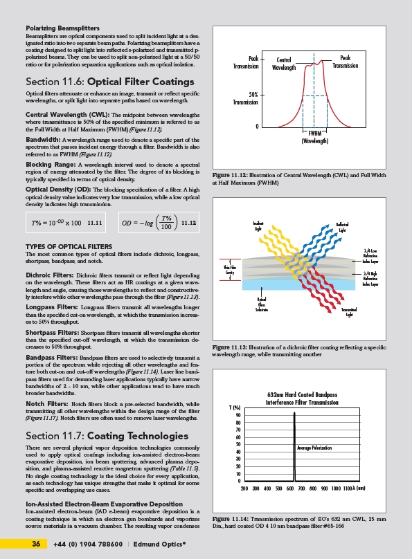
Bandpass Filters: Bandpass fi lters are used to selectively transmit a
portion of the spectrum while rejecting all other wavelengths and feature
both cut-on and cut-off wavelengths (Figure 11.14). Laser line bandpass
fi lters used for demanding laser applications typically have narrow
bandwidths of 2 - 10 nm, while other applications tend to have much
broader bandwidths.
Notch Filters: Notch fi lters block a pre-selected bandwidth, while
transmitting all other wavelengths within the design range of the fi lter
(Figure 11.17). Notch fi lters are often used to remove laser wavelengths.
Section 11.7: Coating Technologies
There are several physical vapor deposition technologies commonly
used to apply optical coatings including ion-assisted electron-beam
evaporative deposition, ion beam sputtering, advanced plasma deposition,
and plasma-assisted reactive magnetron sputtering (Table 11.5).
No single coating technology is the ideal choice for every application,
as each technology has unique strengths that make it optimal for some
specifi c and overlapping use cases.
Ion-Assisted Electron-Beam Evaporative Deposition
Ion-assisted electron-beam (IAD e-beam) evaporative deposition is a
coating technique in which an electron gun bombards and vaporizes
source materials in a vacuum chamber. The resulting vapor condenses
36 +44 (0) 1904 788600 | Edmund Optics®
Central
Wavelength
50%
Transmission
0
Peak
Transmission
FWHM
(Wavelength)
Peak
Transmission
Figure 11.12: Illustration of Central Wavelength (CWL) and Full Width
at Half Maximum (FWHM)
Incident
Light
Reflected
Light
λ/4 Low
Refractive
Index Layer
λ/4 High
Refractive
Index Layer
Transmitted
Light
Thin-Film
Cavity
Optical
Glass
Substrate
Figure 11.13: Illustration of a dichroic fi lter coating refl ecting a specifi c
wavelength range, while transmitting another
11.11 11.12
90
80
70
60
50
40
30
20
10
0
632nm Hard Coated Bandpass
Interference Filter Transmission
Average Polarization
200 300 400 500 600 700 800 900 1000 1100
T (%)
(nm)
Figure 11.14: Transmission spectrum of EO’s 632 nm CWL, 25 mm
Dia., hard coated OD 4 10 nm bandpass fi lter #65-166