Phase shift:
www.edmundoptics.eu/LO 13
Section 4:
Beam Shape, Beam Quality,
and Strehl Ratio
1 x 2
2 x 2
3 x 2
4 x 2
5 x 2
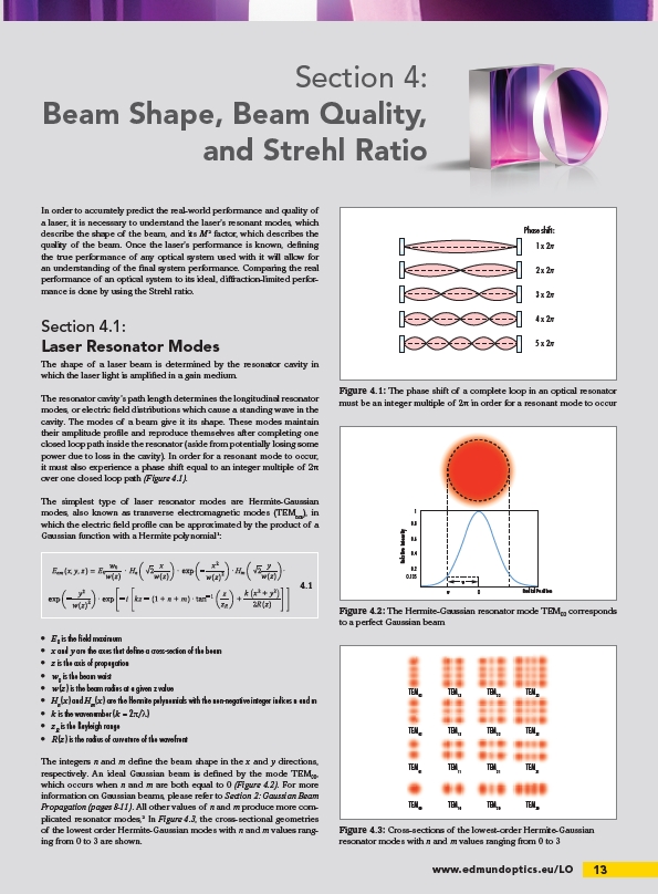
Figure 4.1: The phase shift of a complete loop in an optical resonator
must be an integer multiple of 2π in order for a resonant mode to occur
In order to accurately predict the real-world performance and quality of
a laser, it is necessary to understand the laser’s resonant modes, which
describe the shape of the beam, and its M2 factor, which describes the
quality of the beam. Once the laser’s performance is known, defi ning
the true performance of any optical system used with it will allow for
an understanding of the fi nal system performance. Comparing the real
performance of an optical system to its ideal, diff raction-limited performance
is done by using the Strehl ratio.
Section 4.1:
Laser Resonator Modes
The shape of a laser beam is determined by the resonator cavity in
which the laser light is amplifi ed in a gain medium.
The resonator cavity’s path length determines the longitudinal resonator
modes, or electric fi eld distributions which cause a standing wave in the
cavity. The modes of a beam give it its shape. These modes maintain
their amplitude profi le and reproduce themselves after completing one
closed loop path inside the resonator (aside from potentially losing some
power due to loss in the cavity). In order for a resonant mode to occur,
it must also experience a phase shift equal to an integer multiple of 2π
over one closed loop path (Figure 4.1).
The simplest type of laser resonator modes are Hermite-Gaussian
modes, also known as transverse electromagnetic modes (TEMnm), in
which the electric fi eld profi le can be approximated by the product of a
Gaussian function with a Hermite polynomial1:
• E0 is the fi eld maximum
• x and y are the axes that defi ne a cross-section of the beam
• z is the axis of propagation
• w0 is the beam waist
• w(z) is the beam radius at a given z value
• Hn(x) and Hm(x) are the Hermite polynomials with the non-negative integer indices n and m
• k is the wavenumber (k = 2π/λ)
• zR is the Rayleigh range
• R(z) is the radius of curvature of the wavefront
The integers n and m defi ne the beam shape in the x and y directions,
respectively. An ideal Gaussian beam is defi ned by the mode TEM00,
which occurs when n and m are both equal to 0 (Figure 4.2). For more
information on Gaussian beams, please refer to Section 2: Gaussian Beam
Propagation (pages 8-11). All other values of n and m produce more complicated
resonator modes,2 In Figure 4.3, the cross-sectional geometries
of the lowest order Hermite-Gaussian modes with n and m values ranging
from 0 to 3 are shown.
4.1
1
0.8
0.6
0.4
0.2
0.135
w
w
O
Relative Intensity
Radial Position
Figure 4.2: The Hermite-Gaussian resonator mode TEM00 corresponds
to a perfect Gaussian beam
TEM03 TEM13 TEM23 TEM33
TEM02 TEM12 TEM22 TEM32
TEM01 TEM11 TEM21 TEM31
TEM00 TEM10 TEM20 TEM30
Figure 4.3: Cross-sections of the lowest-order Hermite-Gaussian
resonator modes with n and m values ranging from 0 to 3
/LO