=
www.edmundoptics.eu/LO 53
M1 and M2 are the loss of the two reference mirrors and M3 is the loss
of the test mirror. The loss from air in the cavity is assumed to be negligible.
CRDS is an ideal technique for characterizing the performance of
reflective laser optics because it is much easier to accurately measure a
small amount of loss rather than a large reflectance (Table 16.1). Transmissive
components with anti-reflection coatings can also be tested by
inserting them into a resonant cavity and measuring the corresponding
increase in loss. CRDS must be performed in a clean environment with
meticulous care, as any contamination on the mirrors or to the inside of
the cavity will affect the loss measurements.
Section 16.2:
Interferometry
Interferometers utilize interference to measure small displacements,
surface irregularities, and changes in refractive index. They can measure
surface irregularities <λ/20 and are used to qualify flats, spherical
lenses, aspheric lenses, and other optical components.
Interference occurs when multiple waves of light are superimposed and
added together to form a new pattern. In order for interference to occur,
the multiple waves of light must be coherent in phase and have non-orthogonal
polarization states,1 If the troughs, or low points, of the waves
align they cause constructive interference add their intensities, while if
the troughs of one wave align with the peaks of the other they will cause
destructive interference and cancel each other out (Figure 16.2).
Interferometers typically use a beamsplitter to split light from a single
source into a test beam and a reference beam. The beams are recombined
before reaching a photodetector, and any optical path difference
between the two paths will create interference. This allows for
comparing an optical component in the path of the test beam to a
reference in the reference beam (Figure 16.3). Constructive and destructive
interference between the two paths will create a pattern of
visible interference fringes. Both reflective and transmissive optical
components can be measured by comparing the transmitted or reflected
wavefront to a reference.
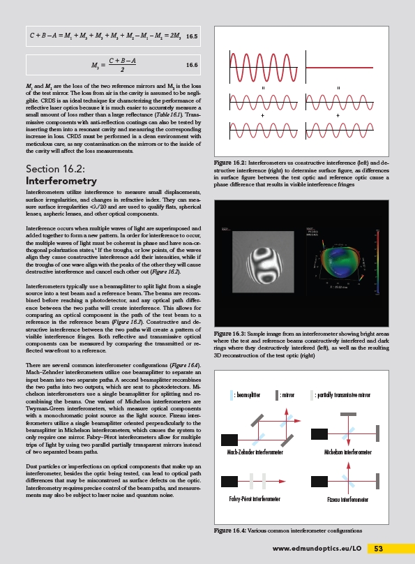
There are several common interferometer configurations (Figure 16.4).
Mach–Zehnder interferometers utilize one beamsplitter to separate an
input beam into two separate paths. A second beamsplitter recombines
the two paths into two outputs, which are sent to photodetectors. Michelson
interferometers use a single beamsplitter for splitting and recombining
the beams. One variant of Michelson interferometers are
Twyman-Green interferometers, which measure optical components
with a monochromatic point source as the light source. Fizeau interferometers
utilize a single beamsplitter oriented perpendicularly to the
beamsplitter in Michelson interferometers, which causes the system to
only require one mirror. Fabry–Pérot interferometers allow for multiple
trips of light by using two parallel partially transparent mirrors instead
of two separated beam paths.
Dust particles or imperfections on optical components that make up an
interferometer, besides the optic being tested, can lead to optical path
differences that may be misconstrued as surface defects on the optic.
Interferometry requires precise control of the beam paths, and measurements
may also be subject to laser noise and quantum noise.
16.5
16.6
=
+ +
Figure 16.2: Interferometers us constructive interference (left) and destructive
interference (right) to determine surface figure, as differences
in surface figure between the test optic and reference optic cause a
phase difference that results in visible interference fringes
Figure 16.3: Sample image from an interferometer showing bright areas
where the test and reference beams constructively interfered and dark
rings where they destructively interfered (left), as well as the resulting
3D reconstruction of the test optic (right)
: beamsplitter : mirror : partially transmissive mirror
Mach-Zehnder interferometer
Fabry-Pérot interferometer
Michelson interferometer
Fizeau interferometer
Figure 16.4: Various common interferometer configurations
/LO