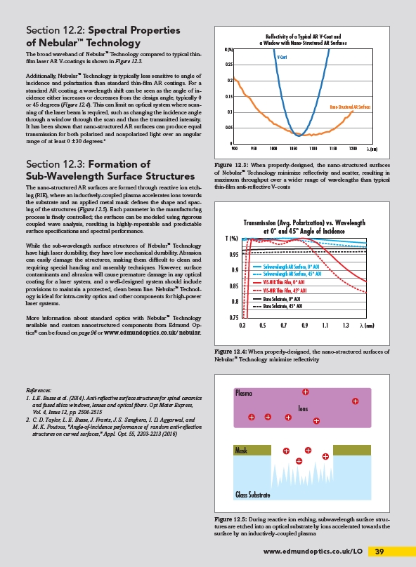
Transmission (Avg. Polarization) vs. Wavelength
at 0° and 45° Angle of Incidence
0.3 0.5 0.7 0.9 1.1 1.3
www.edmundoptics.co.uk/LO 39
Section 12.2: Spectral Properties
of Nebular™ Technology
The broad waveband of Nebular™ Technology compared to typical thinfilm
laser AR V-coatings is shown in Figure 12.3.
Additionally, Nebular™ Technology is typically less sensitive to angle of
incidence and polarization than standard thin-film AR coatings. For a
standard AR coating, a wavelength shift can be seen as the angle of incidence
either increases or decreases from the design angle, typically 0
or 45 degrees (Figure 12.4). This can limit an optical system where scanning
of the laser beam is required, such as changing the incidence angle
through a window through the scan and thus the transmitted intensity.
It has been shown that nano-structured AR surfaces can produce equal
transmission for both polarized and nonpolarized light over an angular
range of at least 0 ±30 degrees.2
Section 12.3: Formation of
Sub-Wavelength Surface Structures
The nano-structured AR surfaces are formed through reactive ion etching
(RIE), where an inductively-coupled plasma accelerates ions towards
the substrate and an applied metal mask defines the shape and spacing
of the structures (Figure 12.5). Each parameter in the manufacturing
process is finely controlled; the surfaces can be modeled using rigorous
coupled wave analysis, resulting in highly-repeatable and predictable
surface specifications and spectral performance.
While the sub-wavelength surface structures of Nebular™ Technology
have high laser durability, they have low mechanical durability. Abrasion
can easily damage the structures, making them difficult to clean and
requiring special handing and assembly techniques. However, surface
contaminants and abrasion will cause premature damage in any optical
coating for a laser system, and a well-designed system should include
provisions to maintain a protected, clean beam line. Nebular™ Technology
is ideal for intra-cavity optics and other components for high-power
laser systems.
More information about standard optics with Nebular™ Technology
available and custom nanostructured components from Edmund Optics
® can be found on page 96 or www.edmundoptics.co.uk/nebular.
References:
1. L.E. Busse et al. (2014). Anti-reflective surface structures for spinel ceramics
and fused silica windows, lenses and optical fibers. Opt Mater Express,
Vol. 4, Issue 12, pp. 2504-2515
2. C. D. Taylor, L. E. Busse, J. Frantz, J. S. Sanghera, I. D. Aggarwal, and
M. K. Poutous, "Angle-of-incidence performance of random anti-reflection
structures on curved surfaces," Appl. Opt. 55, 2203-2213 (2016)
V-Coat
Nano-Structured AR Surfaces
0.25
0.2
0.15
0.1
0.05
0
900
950 1000 1050 1100 1150 1200
R (%)
Reflectivity of a Typical AR V-Coat and
a Window with Nano-Structured AR Surfaces
λ (nm)
Figure 12.3: When properly-designed, the nano-structured surfaces
of Nebular™ Technology minimize reflectivity and scatter, resulting in
maximum throughput over a wider range of wavelengths than typical
thin-film anti-reflective V-coats
T (%)
0.95
0.9
0.85
0.8
0.75
Plasma
Ions
Mask
Glass Substrate
Figure 12.5: During reactive ion etching, subwavelength surface structures
are etched into an optical substrate by ions accelerated towards the
surface by an inductively-coupled plasma
λ (nm)
Subwavelength AR Surface, 0° AOI
Subwavelength AR Surface, 45° AOI
VIS-NIR Thin Film, 0° AOI
VIS-NIR Thin Film, 45° AOI
Bare Substrate, 0° AOI
Bare Substrate, 45° AOI
Figure 12.4: When properly-designed, the nano-structured surfaces of
Nebular™ Technology minimize reflectivity
/LO
/nebular