өIncident өTIR
n2 n1
ө ө Transmitted Reflected
R2 – R1 = λ/2
www.edmundoptics.co.uk/LO 33
The law of reflection states that the angle of a reflected ray, with respect
to the surface normal, is of equal magnitude to the angle of incidence,
but of opposite direction with respect to the surface normal.
If the angle of incidence of a ray passing from one medium to another
with a lower refractive index is larger than the critical angle of a material
(θC) defined by the ratio of the two refractive indices, total internal reflection
will occur and the ray will be completely reflected (Figure 11.4).
The angle of refraction equals 90° when the incident angle is exactly
equal to the critical angle.²
The amplitude coefficients for transmission and reflection at the interface
between two optical media are governed by the Fresnel equations
for transmission and reflection:3
Where ts and tp are the amplitude transmission coefficients for s- and
p-polarization, rs and rp are the amplitude reflection coefficients for s-
and p-polarization, n₁ and n₂ are the refractive indices of the two optical
media, θ₁ is the incident angle, and θ₂ is the transmitted or reflected
angle. At normal incidence, θ₁ and θ2 are 0 making all cosine terms 1
and the amplitude coefficients the same for both polarization states. This
makes intuitive sense as there is no distinction between the s- and ppolarization
states at normal incidence.
Section 11.3: Anti-Reflection Coatings
Due to Fresnel reflection, as light passes from air through an uncoated
glass substrate approximately 4% of the light will be reflected at each
interface. This results in a total transmission of only 92% of the incident
light, which can be extremely detrimental in laser optics applications
(Figure 11.5). Excess reflected laser light reduces throughput and can
lead to laser-induced damage. Anti-reflection (AR) coatings are applied
to optical surfaces to increase the throughput of a system and reduce
hazards caused by reflections that travel backwards through the system
and create ghost images. Back reflections also destabilize laser systems
by allowing unwanted light to enter the laser cavity. AR coatings are
especially important for systems containing multiple transmitting optical
elements. Many low-light systems incorporate AR coated optics to allow
for efficient use of light.
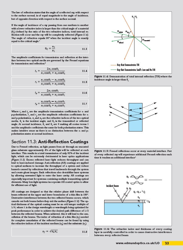
AR coatings are designed so that the relative phase shift between the
beam reflected at the upper and lower boundaries of a thin film is 180°.
Destructive interference between the two reflected beams occurs, which
cancels out both beams before they exit the surface (Figure 11.6). The optical
thickness of the optical coating must be an odd integer multiple of
λ/4, where λ is the design wavelength or wavelength being optimized for
peak performance in order to achieve the desired path difference of λ/2
between the reflected beams. When achieved, this it will lead to the cancellation
of the beams. The index of refraction of a thin film (nf) needed
for complete cancelation of the reflected beams can be found by using
the refractive indices of the incident medium (n0) and the substrate (ns).
Ray that Demonstrates TIR
Ray that Demonstrates Snell’s Law and No TIR
Figure 11.4: Demonstration of total internal reflection (TIR) where the
incidence angle is larger than θc
r2
r1
Figure 11.5: Fresnel reflections occur at every material interface. Part
of every reflected ray will experience additional Fresnel reflection each
time it reaches an additional interface1
11.3
11.4
11.5
11.6
11.7
Incident Beam
R1 R2
no
nf
ns
λ/4
R1:
R2:
Figure 11.6: The refractive index and thickness of every coating
layer is carefully controlled in order to cause destructive interference
between every reflected beam
11.8
/LO