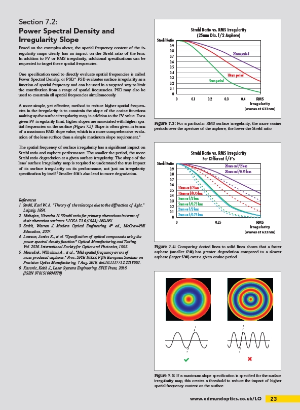
Strehl Ratio vs. RMS Irregularity
(25mm Dia. f/2 Asphere)
20mm period
10mm period
5mm period
0 0.1 0.2 0.3 0.4
(waves at 633nm)
Figure 7.3: For a particular RMS surface irregularity, the more cosine
periods over the aperture of the asphere, the lower the Strehl ratio
Strehl Ratio vs. RMS Irregularity
For Different f/#’s
10mm on f/2 lens
10mm on f/0.75 lens
RMS
Irregularity
www.edmundoptics.co.uk/LO 23
Section 7.2:
Power Spectral Density and
Irregularity Slope
Based on the examples above, the spatial frequency content of the irregularity
maps clearly has an impact on the Strehl ratio of the lens.
In addition to PV or RMS irregularity, additional speci cations can be
requested to target these spatial frequencies.
One speci cation used to directly evaluate spatial frequencies is called
Power Spectral Density, or PSD. PSD evaluates surface irregularity as a
function of spatial frequency and can be used in a targeted way to limit
the contribution from a range of spatial frequencies. PSD may also be
used to constrain all spatial frequencies simultaneously.
A more simple, yet e ective, method to reduce higher spatial frequencies
in the irregularity is to constrain the slope of the cosine functions
making up the surface irregularity map, in addition to the PV value. For a
given PV irregularity limit, higher slopes are associated with higher spatial
frequencies on the surface (Figure 7.5). Slope is often given in terms
of a maximum RMS slope value, which is a more comprehensive evaluation
of the lens surface than a simple maximum slope requirement.
The spatial frequency of surface irregularity has a signi cant impact on
Strehl ratio and asphere performance. The smaller the period, the more
Strehl ratio degradation at a given surface irregularity. The shape of the
lens’ surface irregularity map is required to understand the true impact
of its surface irregularity on its performance, not just an irregularity
speci cation by itself.6 Smaller f/#’s also lead to more degradation.
References
1. Strehl, Karl W. A. “Theory of the telescope due to the di raction of light,”
Leipzig, 1894.
2. Mahajan, Virendra N. "Strehl ratio for primary aberrations in terms of
their aberration variance." JOSA 73.6 (1983): 860-861.
3. Smith, Warren J. Modern Optical Engineering. 4th ed., McGraw-Hill
Education, 2007.
4. Lawson, Janice K., et al. "Speci cation of optical components using the
power spectral density function." Optical Manufacturing and Testing.
Vol. 2536. International Society for Optics and Photonics, 1995.
5. Messelink, Wilhelmus A., et al., "Mid-spatial frequency errors of
mass-produced aspheres," Proc. SPIE 10829, Fifth European Seminar on
Precision Optics Manufacturing, 7 Aug. 2018, doi:10.1117/12.2318663.
6. Kasunic, Keith J., Laser Systems Engineering, SPIE Press, 2016.
(ISBN 9781510604278)
Strehl Ratio
0.9
0.8
0.7
0.6
0.5
0.4
0.3
0.2
0.1
0
0.9
0.8
0.7
0.6
0.5
0.4
0.3
0.2
0.1
0
0 0.25
20mm on f/2 lens
20mm on f/0.75 lens
5mm on f/2 lens
5mm on f/0.75 lens
2mm on f/2 lens
2mm on f/0.75 lens
Strehl Ratio
RMS
Irregularity
(waves at 633nm)
Figure 7.4: Comparing dotted lines to solid lines shows that a faster
asphere (smaller f/#) has greater degradation compared to a slower
asphere (larger f/#) over a given cosine period
Figure 7.5: If a maximum slope speci cation is speci ed for the surface
irregularity map, this creates a threshold to reduce the impact of higher
spatial frequency content on the surface
/LO