Section 16.3:
Atomic Force Microscopy
Atomic force microscopy (AFM) is a technique that provides surface topography
with atomic resolution (Figure 16.5). An extremely small and
sharp tip scans across a sample’s surface, resulting in a 3D reconstruction
of the surface. The tip is attached to a rectangular or triangular
cantilever that connects to the rest of the microscope head. The cantilever’s
motion is controlled by piezoelectric ceramics, which ensures 3D
positioning of the cantilever with subnanometer resolution.2
In laser optics, AFM is primary used to calculate an optical component’s
surface roughness, which may significantly affect the performance of a
laser optical system as it is often the main source of scattering. AFM can
provide a 3D map of a surface with a precision of a few Angstrom’s.3
The tip is either scanned across the sample while in constant contact
with the system, known as contact mode, or in intermittent contact
with the surface, known as tapping mode. In tapping mode, the cantilever
oscillates at its resonant frequency, with the tip only contacting
the surface for a short time during the oscillating cycle. Contact mode
is less complicated than tapping mode and provides a more accurate
reconstruction of the surface. However, the possibility of damaging the
surface during scanning is higher and the tip wears out faster, leading to
a shorter lifetime of the tip. In both modes, a laser is refl ected off the top
of the cantilever onto a detector. Changes in the height of the sample
surface defl ect the cantilever and change the position of the laser on the
detector, generating an accurate height map of the surface (Figure 16.6).
The shape and composition of the tip play a key role in the spatial resolution
of AFM and should be chosen according to the specimen requiring
a scan. The smaller and sharper the tip, the higher the lateral resolution.
However, small tips have longer scanning times and a higher cost
than larger tips.
Control of the distance between the tip and the surface determines the
vertical resolution of an AFM system. Mechanical and electrical noise
limit the vertical resolution as surface features smaller than the noise
level cannot be resolved.4 The relative position between the tip and the
sample is also sensitive to the expansion or contraction of AFM components
as a result of thermal variations.
AFM is a time-consuming metrology technique and is mainly used for
process validation and monitoring, where a small fraction of a sample
surface on the order of 100μm x 100μm is measured to provide a statistically
signifi cant representation of its manufacturing process as a whole.
Section 16.4:
White Light Interferometry for
Superpolished Surface Roughness
Measurement
White light interferometry (WLI) can also be used to measure surface
roughness. The combination of AFM and WLI allows optical fabricators
to measure surface topography over a wide range of spatial frequencies,
even measuring the sub-angstrom RMS surface roughness of superpolished
surfaces.
Most interferometers utilize a monochromatic laser as the illumination
source because the laser’s long coherence length makes it easy
to observe interference fringes, but white light interferometers utilize a
broadband illumination source to analyze surface height. Surface height
can be measured because the interference at a given location is highest
when the reference and measured optical path lengths are equal, so
modulating the distance between the WLI and the test surface generates
surface topography data. White light interferometers are typically Michelson
interferometer setups with the test optic placed in one arm and
a reference optic in the other (Figure 16.7). The length of the reference
54 +44 (0) 1904 788600 | Edmund Optics®
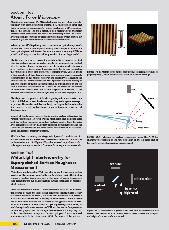
Figure 16.5: Atomic force microscopy produces nanometer-level topography
maps, which can be useful for characterizing gratings
Laser
Detector
Sharp tip
Cantilever
Sample surface
Figure 16.6: Changes in surface topography move the AFM tip,
changing the position of the refl ected laser on the detected and allowing
for surface topography measurement
broadband
source
test mirror
reference mirror
test surface
height varied
Figure 16.7: Schematic of a typical white light Michelson interferometer
used to determine surface roughness. The instrument is kept stationary as
the height of the test surface is varied