Reflected Light: Combination of 6 Beams
R1 R1:
Metallic Mirror Coatings
R2:
nL - low index
Coating Description Specifi cations
UV Enhanced Aluminum
Ravg >89% @ 250 - 450nm
Ravg >85% @ 250 - 700nm
Protected Aluminum
Ravg >85% @ 400 - 700nm
Ravg >90% @ 400 - 2000nm
Enhanced Aluminum Ravg >95% @ 450 - 650nm
Protected Silver
Ravg >98% @ 500 - 800nm
Ravg >98% @ 2000 - 10,000nm
Ultrafast Enhanced Silver Ravg >96% @ 600 - 1000nm
Protected Gold
Ravg >96% @ 700 - 2000nm
Ravg >96% @ 2000 - 10,000nm
Standard HR Laser Coatings *See website for full coating list
DWL Refl ectivity Specifi cations
LIDT, Pulsed
(J/cm²)
LIDT, CW
(MW/cm²)
266nm Rabs >99.5% @ DWL, Ravg >99.5% 263 - 268nm 2.5, 20ns @ 20Hz 1
343nm Rabs >99.8% @ DWL, Ravg >99.5% 339 - 346nm 6, 20ns @ 20Hz 1
355nm Rabs >99.8% @ DWL, Ravg >99.5% 351 - 358nm 6, 20ns @ 20Hz 1
515nm Rabs >99.8% @ DWL, Ravg >99.5% 509 - 520nm 15, 20ns @ 20Hz 1
532nm Rabs >99.8% @ DWL, Ravg >99.5% 523 - 537nm 15, 20ns @ 20Hz 1
1064nm Rabs >99.8% @ DWL, Ravg >99.5% 1046 - 1074nm 20, 20ns @ 20Hz 1
www.edmundoptics.co.uk/LO 35
Incident
Light
Transmitted Light
n = 1 - air
nH - high index
nL - low index
nH - high index
nH - high index
nS - substrate
R2
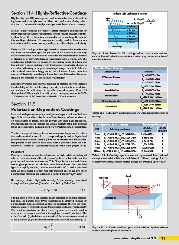
Figure 11.10: Dielectric HR coatings utilize constructive interference
of Fresnel refl ections to achieve a refl ectivity greater than that of
metallic refl ectors
Table 11.3: Refl ectivity specifi cations for EO’s standard metallic mirror
coatings
Table 11.4: Refl ectivity specifi cations and guaranteed laser induced
damage thresholds for EO’s standard dielectric HR laser coatings. For other
laser wavelengths, custom coating designs are available upon request
Section 11.4: Highly-Refl ective Coatings
Highly-refl ective (HR) coatings are used to minimize loss while refl ecting
lasers and other light sources. Absorption and scatter during refl ection
lead to decreased throughput and potential laser-induced damage.
Metallic mirror coatings are used to create refl ective components for
many applications but laser applications tend to require a higher refl ectivity
than those off ered from standard metallic mirror coatings. Because of
this, multilayer dielectric HR coatings are usually used for laser mirrors
instead of metallic mirror coatings, as they can achieve higher refl ectivity.
Dielectric HR coatings refl ect light based on constructive interference
and have the complete opposite purpose of AR coatings in that they
utilize constructive interference to maximize Fresnel refl ections instead
of utilizing destructive interference to minimize them (Figure 11.10). The
constructive interference is caused by alternating layers of a high and
low refractive index materials with thicknesses specifi cally chosen to
maximize refl ectivity at a given wavelength range. In a λ/4 dielectric
mirror, also known as a Bragg mirror, the thickness of each layer is a
quarter of the design wavelength. Layer thickness is based on the wavelength
in the material, not the vacuum wavelength.3
Dielectric overcoats also improve handling of metallic mirrors, increase
the durability of the metal coating, provide protection from oxidation,
and enhance the refl ectance in specifi c spectral regions. Table 11.3
shows a list of EO’s standard metallic mirror coating options, while Table
11.4 shows a list of EO’s standard dielectric HR laser coatings.
Section 11.5:
Polarization-Dependent Coatings
Polarization-dependent coatings manipulate the polarization of incident
light. Polarization aff ects the focus of laser beams, infl uences the cutoff
wavelengths of fi lters, and can prevent unwanted back refl ections.
Polarization-dependent coatings are usually dielectric thin-fi lm coatings
found on components such as polarizers, waveplates, and beamsplitters.
The two orthogonal linear polarization states most important for refl ection
and transmission are referred to as p- and s-polarization. P-polarized
(from the German word “parallel”) light has an electric fi eld that is polarized
parallel to the plane of incidence, while s-polarized (from the German
word “senkrecht”) light is perpendicular to this plane (Figure 11.11).
Polarizers
Polarizers transmit a specifi c polarization of light while excluding all
others. There are many diff erent types of polarizers, but only thin fi lm
polarizers utilize an optical coating. Thin fi lm polarizers are available as
coated glass plates or as polarizing cube beamsplitters. Non-polarized
light is a rapidly varying, random combination of p- and s-polarized
light. An ideal linear polarizer will only transmit one of the two linear
polarizations, reducing the initial non-polarized intensity I0 by half.5
For linearly polarized light with intensity I0, the intensity transmitted
through an ideal polarizer (I) can be described by Malus’ law:5
θ is the angle between the incident linear polarization and the polarization
axis. For parallel axes, 100% transmission is achieved, though for
perpendicular axes, also known as crossed polarizers, there is 0% transmission.
In real world applications, transmission will never reach exactly
0%, therefore polarizers are characterized by an extinction ratio used to
determine the actual transmission through two crossed polarizers. The
extinction ratio (ρp) is defi ned as the ratio of the minimum transmission
of the polarizer (T2) to the maximum transmission of the polarizer (T1):
S
P
Normal
Plane of Incidence
Incident Light
Incident Surface
Figure 11.11: P and s are linear polarizations defi ned by their relative
orientation to the plane of incidence
11.9
11.10
/LO