22 +44 (0) 1904 788600 | Edmund Optics®
Section 7:
Aspheric Lens
Irregularity and
Strehl Ratio
All optical systems have a theoretical performance limit known as the diffraction
limit. Strehl ratio is a speci cation used to compare the real performance
of an optical system with its di raction-limited performance.
For aspheric lenses and other focusing optics, Strehl ratio is de ned as
the ratio of peak focal spot irradiance of the manufactured optic to the
di raction-limited peak irradiance (Figure 7.1).1 Di erent aspheric lens
manufacturing techniques impart unique surface errors that a ect Strehl
ratio di erently. Understanding these e ects is important to correctly
specify aspheres, preventing unnecessary and costly overspeci cation
while ensuring that desired speci cations are met. This becomes increasingly
crucial for fast aspheres with small f/#'s, and a ects aspheres
manufactured through conventional grinding and polishing more than
those made through other methods. The industry standard threshold to
classify a lens as “di raction-limited” is a Strehl ratio greater than 0.8.
Strehl ratio can also be related to RMS transmitted wavefront error using
the following approximation, where σ is RMS wavefront error in waves.
This approximation is valid for transmitted wavefront error values
<0.2 waves.3
7.1
Section 7.1:
Impact of Surface Irregularity on
Strehl Ratio
The Strehl ratio of an optic is highly dependent on its surface irregularity,
or the deviation of the optical surface from its nominal form; surface irregularity
is a result of the manufacturing method used. Spherical optics
are typically polished using an oversized tool, which imparts low spatial
frequency errors on the optical surface. Aspherical lens manufacturing,
however, typically utilizes subaperture grinding and polishing, creating
a more complex irregularity structure. Understanding the relationship
between a speci ed surface irregularity and its underlying structure can
provide insight into the lens' performance and resulting Strehl ratio.
For example, consider the impact of spatial frequency. When surface
irregularity is modeled as a rotationally-symmetric cosine function, we
can explore the resulting Strehl ratio as a function of RMS surface irregularity
for a variety of cosine periods (Figure 7.2 and Figure 7.3).
The key factor here is not the period of the cosine in mm, but the number
of periods over the aperture of the lens. For a given subaperture tool
used in asphere manufacturing, smaller diameter aspheres will have less
Strehl ratio degradation compared to larger diameter aspheres.
The impact of surface irregularity on Strehl ratio is also dependent on
the f/# of the lens. As a general rule, faster aspheres, or aspheres with
smaller f/#’s, have greater sensitivity to surface irregularity’s impact on
Strehl ratio. For example, Figure 7.4 compares an f/2 lens to an f/0.75
lens (both with 25mm diameter), and more Strehl ratio degradation
is seen for the faster lenses compared to the slower lenses at a given
cosine period.
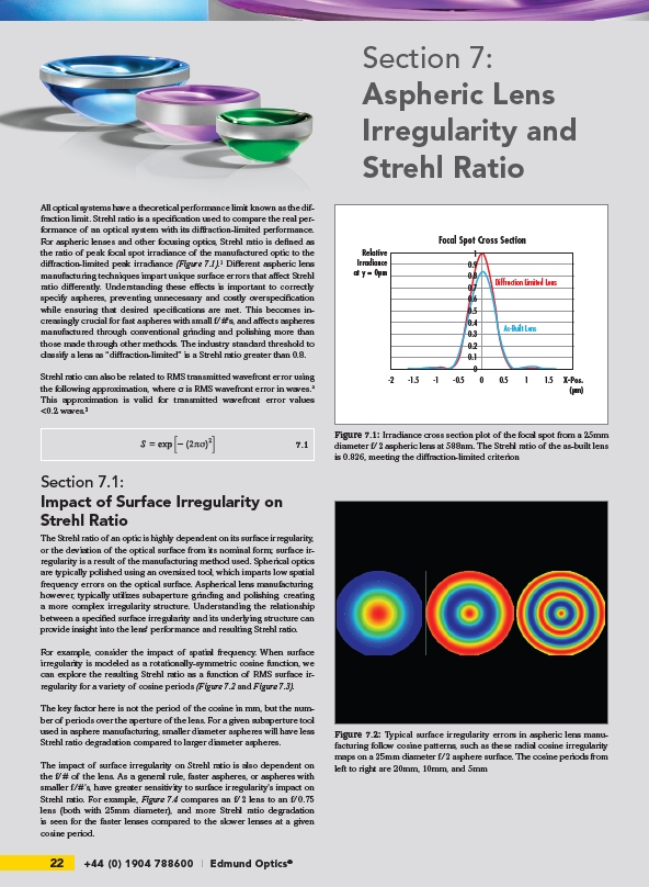
Focal Spot Cross Section
Diffraction Limited Lens
As-Built Lens
1
0.7
0.5
0.4
0.3
0.2
0.1
-2 -1.5 -1 -0.5 0 0.5 1 1.5
Relative
Irradiance
at y = 0m
X-Pos.
(m)
0.9
0.8
0.6
0
Figure 7.1: Irradiance cross section plot of the focal spot from a 25mm
diameter f/2 aspheric lens at 588nm. The Strehl ratio of the as-built lens
is 0.826, meeting the di raction-limited criterion
Figure 7.2: Typical surface irregularity errors in aspheric lens manufacturing
follow cosine patterns, such as these radial cosine irregularity
maps on a 25mm diameter f/2 asphere surface. The cosine periods from
left to right are 20mm, 10mm, and 5mm