TECHNICAL NOTE
Types of Beamsplitters
Beamsplitters are optical components used to split incident light at a designated ratio into two separate
beams. Additionally, beamsplitters can be used in reverse to combine two different beams into a single
one. Beamsplitters are often classified according to their construction: cube or plate.
Beamsplitter Selection Guide
Shape Beamsplitter Type Wavelength Range Options Surface Flatness Size Range Page
Cube Broadband Non-Polarizing VIS, NIR, Telecom λ/8 5 - 50mm 186
Cube Broadband Polarizing VIS, NIR λ/8 5 - 50mm 186
Cube Laser Line Non-Polarizing 532, 632, 1064nm λ/8 5 - 25mm 187
Cube Laser Line Polarizing 488, 532, 632.8, 780, 850, 980, 1064nm λ/4 5 - 50mm 187
Cube 30R/70T, 50R/50T, 70R/30T VIS λ/4 5 - 50mm 188
Cube High Energy Polarizing 355, 532, 1064nm λ/6 12.7, 25.4mm 188
Cube Wire Grid Polarizing VIS λ/3 10 - 25.4mm 189
Lateral Displacement Non-Polarizing and Polarizing VIS, NIR, 632.8nm λ/8 10, 20mm 189
Wedged Plate 30R/70T, 50R/50T, 70R/30T VIS λ/10 25, 50mm 189
Plate 20R/80T, 30R/70T, 40R/60T, 50R/50T,
60R/40T, 70R/30T, 80R/20T UV, VIS, NIR 1λ, 4-6λ 12.5 - 75mm 190-191
Elliptical Plate 50R/50T VIS, NIR 1λ 12.5 - 50mm 191
Plate 50R/50T 0.8 - 6μm, 2 - 20μm 3/4λ 25, 50mm 192
Plate Laser Line Non-Polarizing 355, 532, 770 - 830, 1064nm λ/8 25.4mm 192
Plate 90/10, 70/30, 50/50 715 - 980, 680 - 1020, 650 - 1050 λ/8 12.7, 25.4mm 193
Plate Ultrafast Harmonic Separator 266, 343, 400, 515 λ/8 25.4mm 193
Plate Nd:YAG Harmonic Separator 266, 355, 532, 1064 λ/10 12.7, 25.4mm 193
Plate Polka Dot 30R/70T, 50R/50T, 70R/30T UV-NIR – 12.7 - 50.8mm 194
Plate Polka Dot 50R/50T, 30R/70T VIS-NIR – 12.7, 25.4mm 194
Pellicle 8R/92T, 40R/40T, 33R/67T, 50R/50T VIS, 632.8nm – 25.4 - 152.4mm 194
Shop www.edmundoptics.co.uk – latest pricing – availability – new products – over 34,000 items 185
lenses
optical assemblies mirrors windows diffusers filters polarizers beamsplitters prisms and gratings
cleaning and
handling
Incident
Light
Beamsplitter
Coating
%
% Transmitted
Reflected
d 0.329t
%
%
d
45°
t
Incident
Light
Reflected
Beamsplitter
Coating
Transmitted
Cube Beamsplitters Plate Beamsplitters
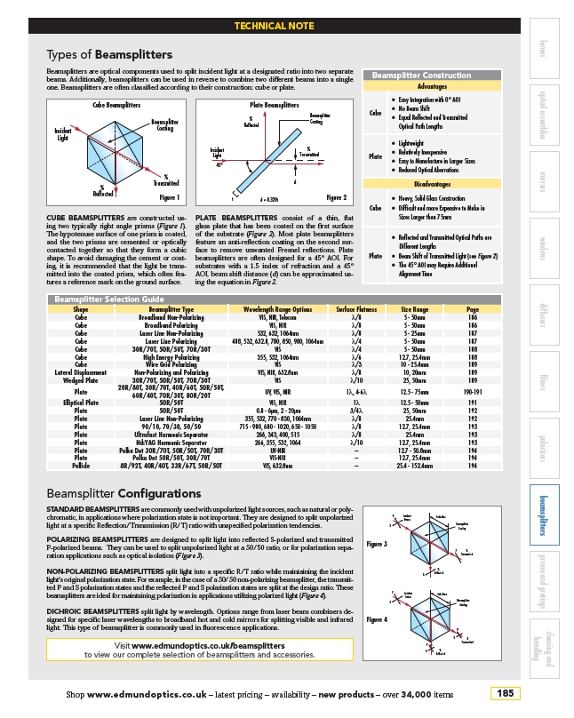
CUBE BEAMSPLITTERS are constructed using
two typically right angle prisms (Figure 1).
The hypotenuse surface of one prism is coated,
and the two prisms are cemented or optically
contacted together so that they form a cubic
shape. To avoid damaging the cement or coating,
it is recommended that the light be transmitted
into the coated prism, which often features
a reference mark on the ground surface.
PLATE BEAMSPLITTERS consist of a thin, flat
glass plate that has been coated on the first surface
of the substrate (Figure 2). Most plate beamsplitters
feature an anti-reflection coating on the second surface
to remove unwanted Fresnel reflections. Plate
beamsplitters are often designed for a 45° AOI. For
substrates with a 1.5 index of refraction and a 45°
AOI, beam shift distance (d) can be approximated using
the equation in Figure 2.
Beamsplitter Construction
Advantages
Cube
• Easy Integration with 0° AOI
• No Beam Shift
• Equal Reflected and Transmitted
Optical Path Lengths
Plate
• Lightweight
• Relatively Inexpensive
• Easy to Manufacture in Larger Sizes
• Reduced Optical Aberrations
Disadvantages
Cube
• Heavy, Solid Glass Construction
• Difficult and more Expensive to Make in
Sizes Larger than 75mm
Plate
• Reflected and Transmitted Optical Paths are
Different Lengths
• Beam Shift of Transmitted Light (see Figure 2)
• The 45° AOI may Require Additional
Alignment Time
Beamsplitter Configurations
STANDARD BEAMSPLITTERS are commonly used with unpolarized light sources, such as natural or polychromatic,
in applications where polarization state is not important. They are designed to split unpolarized
light at a specific Reflection/Transmission (R/T) ratio with unspecified polarization tendencies.
POLARIZING BEAMSPLITTERS are designed to split light into reflected S-polarized and transmitted
P-polarized beams. They can be used to split unpolarized light at a 50/50 ratio, or for polarization separation
applications such as optical isolation (Figure 3).
NON-POLARIZING BEAMSPLITTERS split light into a specific R/T ratio while maintaining the incident
light’s original polarization state. For example, in the case of a 50/50 non-polarizing beamsplitter, the transmitted
P and S polarization states and the reflected P and S polarization states are split at the design ratio. These
beamsplitters are ideal for maintaining polarization in applications utilizing polarized light (Figure 4).
DICHROIC BEAMSPLITTERS split light by wavelength. Options range from laser beam combiners designed
for specific laser wavelengths to broadband hot and cold mirrors for splitting visible and infrared
light. This type of beamsplitter is commonly used in fluorescence applications.
Incident
Beam
%
Transmitted
%
S Reflected
P
S
P
Cube Size
Beamsplitter
Coating
Figure 1 Figure 2
Figure 3
Incident
Beam
Cube Size
Beamsplitter
Coating
%
Transmitted
%
Reflected
P
S
P
S
P
S
Figure 4
Visit www.edmundoptics.co.uk/beamsplitters
to view our complete selection of beamsplitters and accessories.
/www.edmundoptics.co.uk
/beamsplitters