112 +44 (0) 1904 788600 | Edmund Optics® N NEW PRODUCT NEW LOW PRICE
testing & detection targets illumination cameras imaging lenses microscopy lasers optomechanics optics
SELECTION GUIDE
Windows Selection Guide
Edmund Optics® (EO) offers a wide variety of windows that are suitable
for applications in the ultraviolet, visible, and infrared wavelength ranges.
Selecting the appropriate window is critical to application success. Key
considerations include the substrate material, coating options, and
optical and mechanical precision.
Substrate Material:
Key considerations when selecting a window substrate include the material’s
refractive index, dispersion, and transmission range.
Refractive index is a description of how light slows down as it passes
through an optical material. Materials with a low index of refraction are
commonly referred to as "crowns", and those materials feature less uncoated
reflection than do materials with a high index of refraction. For
most window applications, a low refractive index is preferred.
Dispersion is a description of the variation of the refractive index with
wavelength. It is specified using the Abbe number, νd, and measured with
the refractive indices at 486,1 nm (Hydrogen F-line), 587,6 nm (Helium dline)
and 656,3 nm (Hydrogen C-line). A low Abbe number indicates high
dispersion. For most window applications, a low dispersion is preferred.
Transmission Range is a description of the usable spectrum over which
a material will exhibit low absorption. While transmission needs will vary
depending on application, Edmund Optics® typically defines the transmission
range as the range of wavelengths over which a material exhibits less
than 25% absorption. For most window applications, a broad transmission
range is preferred.
Coating Options:
As light passes from air through an uncoated window, some portion of the
light will be reflected due to a phenomenon known as Fresnel Reflection.
The greater the refractive index of the window, the greater that loss from
reflection will be. Low refractive index materials have a loss of approximately
8% in the visible spectrum, while higher index materials, such as
Zinc Sulfide (ZnS) will have a loss of >30%. This loss can be minimized
by selecting the right anti-reflection (AR) coating. EO offers 3 types of AR
coatings – Single Layer, Broadband (BBAR), and V-Coat.
Single Layer Coatings are the simplest AR coatings available. A single
thin layer of a dielectric material, typically Magnesium Fluoride (MgF2),
is deposited on each side of the window to reduce the Fresnel Reflection.
The thickness is carefully chosen to reduce the reflection at the design
wavelength (typically the center of the visible spectrum, 550 nm). A single
layer MgF2 coating can increase the transmission of an optical window
from ~92% to ~97%, providing exceptional value at a low cost.
Broadband (BBAR) Coatings combine multiple layers of multiple dielectric
materials, to ensure a highly transmissive window over a broad wavelength
range. EO offers a wide variety of BBAR coatings for applications in
the ultraviolet (UV), ultraviolet-visible (UV-VIS), visible (VIS), visible-near
infrared (VIS-NIR), near infrared (NIR), mid wave infrared (MWIR), and
long wave infrared (LWIR) spectra.
These coatings can increase the transmission of an optical window from
~92% to >99%, providing exceptional performance. They are, however,
more complicated and more expensive than single layer coatings, and
they will provide much lower transmission than either a single layer coated
or uncoated window at wavelengths outside of the design region of
the coating.
V-Coat AR Windows combine multiple layers of multiple dielectric material
to ensure exceptionally high transmission over a narrow wavelength
range. EO offers a wide variety of V-Coats at common laser lines in the
UV, VIS, and NIR. These coatings can increase the transmission of an optical
window from ~92% to >99,5%, providing exceptional performance.
They are, however, more complicated and more expensive than single
layer coatings, and they will provide much lower transmission than either
a single layer coated or uncoated window at wavelengths outside of the
narrow design region of the coating.
Optical and Mechanical Precision:
Optical Windows are often used as protective barriers to separate sensors,
detectors, or other sensitive components from an external environment.
The precision required of that window is application specific. Precision
considerations should include the window’s Surface Flatness, Surface
Quality, and Parallelism.
Surface Flatness, sometimes specified as a surface irregularity or transmitted
wavefront error, is a measure of how flat each of the surfaces of the
windows are. Typically measured in “waves” relative to 632,8 nm, a surface
flatness of 1/10th wave is equivalent to 63,28 nm flatness. As a general rule
of thumb, 1/10th wave or better windows are preferred for laser applications,
¼ wave or better windows are preferred for imaging applications, and less
precise windows are preferred for illumination or detection applications.
Surface Quality is an evaluation of the surface imperfections, such as
scratches and pits, or digs, which may be caused during the manufacturing
or handling process. Per MIL-PRF-13830B, surface quality is described by
a “scratch” number, detailing the brightness of scratches, followed by a
“dig” number, measuring the largest component dig in 1/100th millimeters.
In practical terms, surface qualities of 10-5 and 20-10 are nearly impossible
to see, and are typically reserved for laser applications. Surface qualities
of 40-20 are barely visible, and are often specified for imaging applications.
And surface qualities of 60-40 or 80-50 are fairly easy to see, but still
appropriate for illumination or detection applications.
Parallelism is the measure of deviation in alignment of the two surfaces
of an optical window. Windows that are manufactured utilizing doubleside
polishing are typically highly parallel (<5 arcseconds). Windows
that are manufactured utilizing single-side polishing are typically somewhat
parallel (<5 arcminutes). And windows that are not polished (e.g.,
BOROFLOAT® substrate windows) have an unspecified parallelism. Highly
parallel windows are recommended for imaging applications. Lower
levels of parallelism are typically recommended for laser applications.
And unspecified parallelism is generally appropriate for illumination and
detection applications.
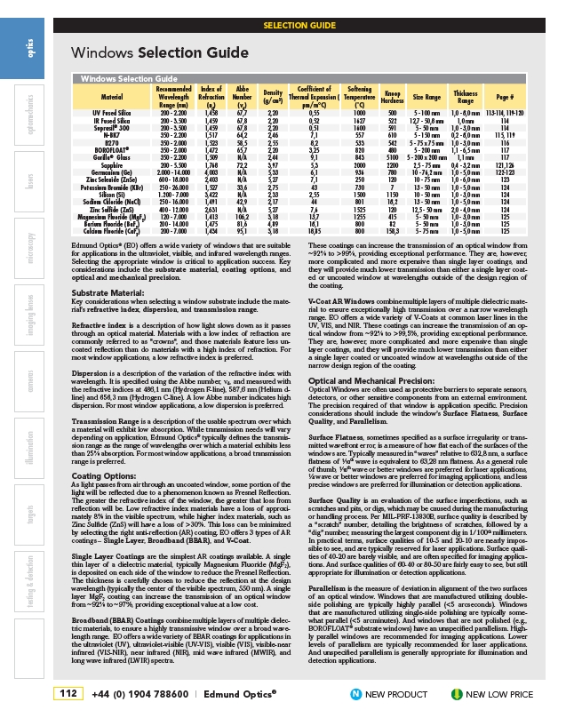
Windows Selection Guide
Material
Recommended
Wavelength
Range (nm)
Index of
Refraction
(nd)
Abbe
Number
(vd)
Density
(g/cm3)
Coefficient of
Thermal Expansion (
μm/m°C)
Softening
Temperature
(˚C)
Knoop
Hardness Size Range Thickness
Range Page #
UV Fused Silica 200 - 2.200 1,458 67,7 2,20 0,55 1000 500 5 - 100 mm 1,0 - 8,0 mm 113-114, 119-120
IR Fused Silica 200 - 3.500 1,459 67,8 2,20 0,52 1627 522 12,7 - 50,8 mm 1,0 mm 114
Suprasil® 300 200 - 3.500 1,459 67,8 2,20 0,51 1600 591 5 - 50 mm 1,0 - 3,0 mm 114
N-BK7 350 - 2.200 1,517 64,2 2,46 7,1 557 610 5 - 150 mm 0,2 - 8,0 mm 115, 119
B270 350 - 2.000 1,523 58,5 2,55 8,2 533 542 5 - 75 x 75 mm 1,0 - 3,0 mm 116
BOROFLOAT® 350 - 2.000 1,472 65,7 2,20 3,25 820 480 5 - 200 mm 1,1 - 6,5 mm 117
Gorilla® Glass 350 - 2.200 1,509 N/A 2,44 9,1 843 5100 5 - 200 x 200 mm 1,1 mm 117
Sapphire 200 - 5.500 1,768 72,2 3,97 5,3 2000 2200 2,5 - 75 mm 0,4 - 3,2 mm 121,126
Germanium (Ge) 2.000 - 14.000 4,003 N/A 5,33 6,1 936 780 10 - 76,2 mm 1,0 - 5,0 mm 122-123
Zinc Selenide (ZnSe) 600 - 18.000 2,403 N/A 5,27 7,1 250 120 10 - 75 mm 1,0 - 6,0 mm 123
Potassium Bromide (KBr) 250 - 26.000 1,527 33,6 2,75 43 730 7 13 - 50 mm 1,0 - 5,0 mm 124
Silicon (Si) 1.200 - 7.000 3,422 N/A 2,33 2,55 1500 1150 10 - 50 mm 1,0 - 3,0 mm 124
Sodium Chloride (NaCl) 250 - 16.000 1,491 42,9 2,17 44 801 18,2 13 - 50 mm 1,0 - 5,0 mm 124
Zinc Sulfide (ZnS) 400 - 12.000 2,631 N/A 5,27 7,6 1525 120 12,5 - 50 mm 2,0 - 4,0 mm 124
Magnesium Fluoride (MgF2) 120 - 7.000 1,413 106,2 3,18 13,7 1255 415 5 - 50 mm 1,0 - 3,0 mm 125
Barium Fluoride (BaF2) 200 - 14.000 1,475 81,6 4,89 18,1 800 82 5 - 50 mm 1,0 - 3,0 mm 125
Calcium Fluoride (CaF2) 200 - 7.000 1,434 95,1 3,18 18,85 800 158,3 5 - 75 mm 1,0 - 5,0 mm 125